This morning we adjusted the offsets of the B7/B8 PD and QPD and we tuned the alignment of the B7 and B8 beams on their sensors (PD, QPD, cameras).
The centering on the sensors was adjusted using the picomotors without changing the nominal angular setpoints of the bench. However we scanned the angular position of the benches in order to check that the PD were well centered.
For SNEB the nominal angular position (which corresponds also to a good alignment of the green beam) is : TY = -130 urad, TX = -565 urad.
The horizontal centering on the PD was refined with -1000 steps on picomotor B7_Mmot3_H and -2500 steps on picomotor B7_Mmot4_H.
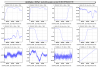
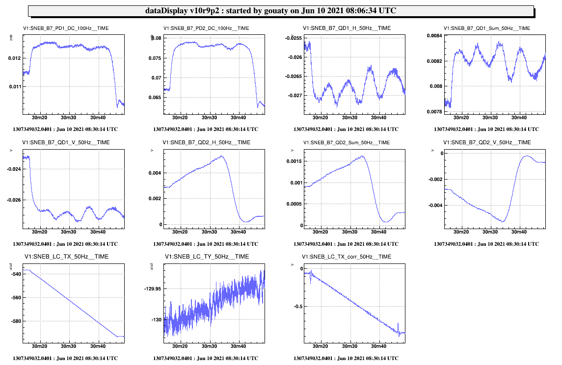
Fig.1 shows a scan of the SNEB bench in TY: the setpoint TY = -130 urad corresponds to the center of the plateau on both PD1 and PD2.
The vertical centering on the PD was refined with -3700 steps on picomotor B7_Mmot3_V and +12900 steps on picomotor B7_Mmot4_V.
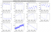
Fig.2 shows a scan of the SNEB bench in TX: the setpoint TX = -565 urad corresponds to the center of the plateau on both PD1 and PD2.
Then the B7 beam was put at the center of the both Cam1 and Cam2.
The quadrants QD1 and QD2 were also centered with the following picomotor steps:
B7_Mmot1_V: -18400 steps ; B7_Mmot1_H: -17750 steps
B7_Mmot2_V: -14450 steps ; B7_Mmot2_H: +13900 steps
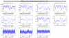
Fig.3 shows the DC powers on the B7 PD and QPD after this alignment.
One point to check is if the realignment of QD2 could have misaligned the beam going to the new silicon beam dump. To answer this question we can make a quick calculation: 14000 steps on the Mmot2 picomotor stands for a displacement of the picomotor of 420 um. Considering that the picomotor axis is ~50 mm away from the point where the mirror mount is attached, the induced tilt is equal to 420/50000 = 0.0084 rad. The beam dump is located approximatively at a distance of ~700 mm from the Mmot2 mirror. Thus the beam position on the beam dump may have shift by 2*0.0084*700 = 12 mm. For comparison the silicon beam dump has a diameter aperture of 40 mm. Moreovoer the beam was centered on the beam dump and at the same time on the quadrant last saturday (https://logbook.virgo-gw.eu/virgo/?r=52050). Thus the beam remains inside the silicon beam dump.
For SWEB the nominal angular position (which corresponds also to a good alignment of the green beam) is : TY = 1780 urad, TX = 115 urad.
We noticed that the B8_PD1 photodiode was really miscentered, as almost no power was reaching it. The horizontal centering on the two PD was corrected with +11000 steps on picomotor B8_Mmot3_H and +27000 steps on picomotor B8_Mmot4_H.
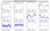
Fig.4 shows a scan of the SWEB bench in TY: the setpoint TY = 1780 urad corresponds to the center of the plateau on both PD1 and PD2.
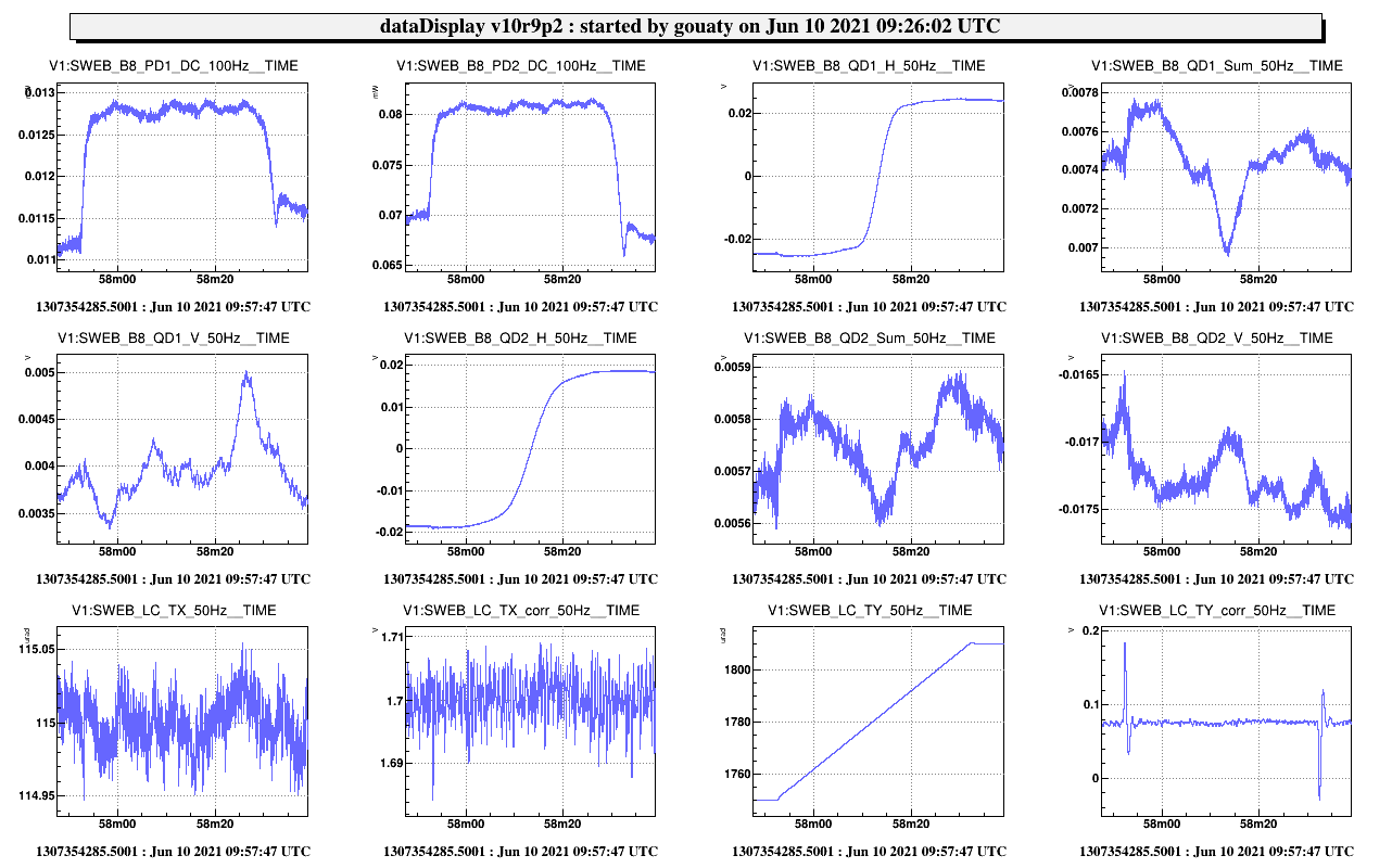
The vertical centering on the PD was already very good, it did not need to be refined. Fig.5 shows a scan of the SWEB bench in TX: the setpoint TX = 115 urad corresponds to the center of the plateau on both PD1 and PD2.
Then the B8 beam was put at the center of the both Cam1 and Cam2.
The quadrants QD1 and QD2 were also centered with the following picomotor steps:
B8_Mmot1_V: 1000 steps ; B8_Mmot1_H: 1290 steps
B8_Mmot2_V: -6050 steps ; B7_Mmot2_H: 0 steps
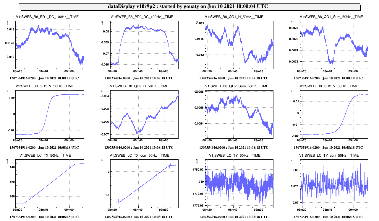
Fig.6 shows the DC powers on the B8 PD and QPD after this alignment.
