I am attaching a PDF file that briefly explains what has been done, with some final remarks.
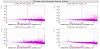
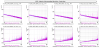
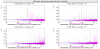
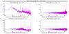
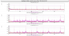
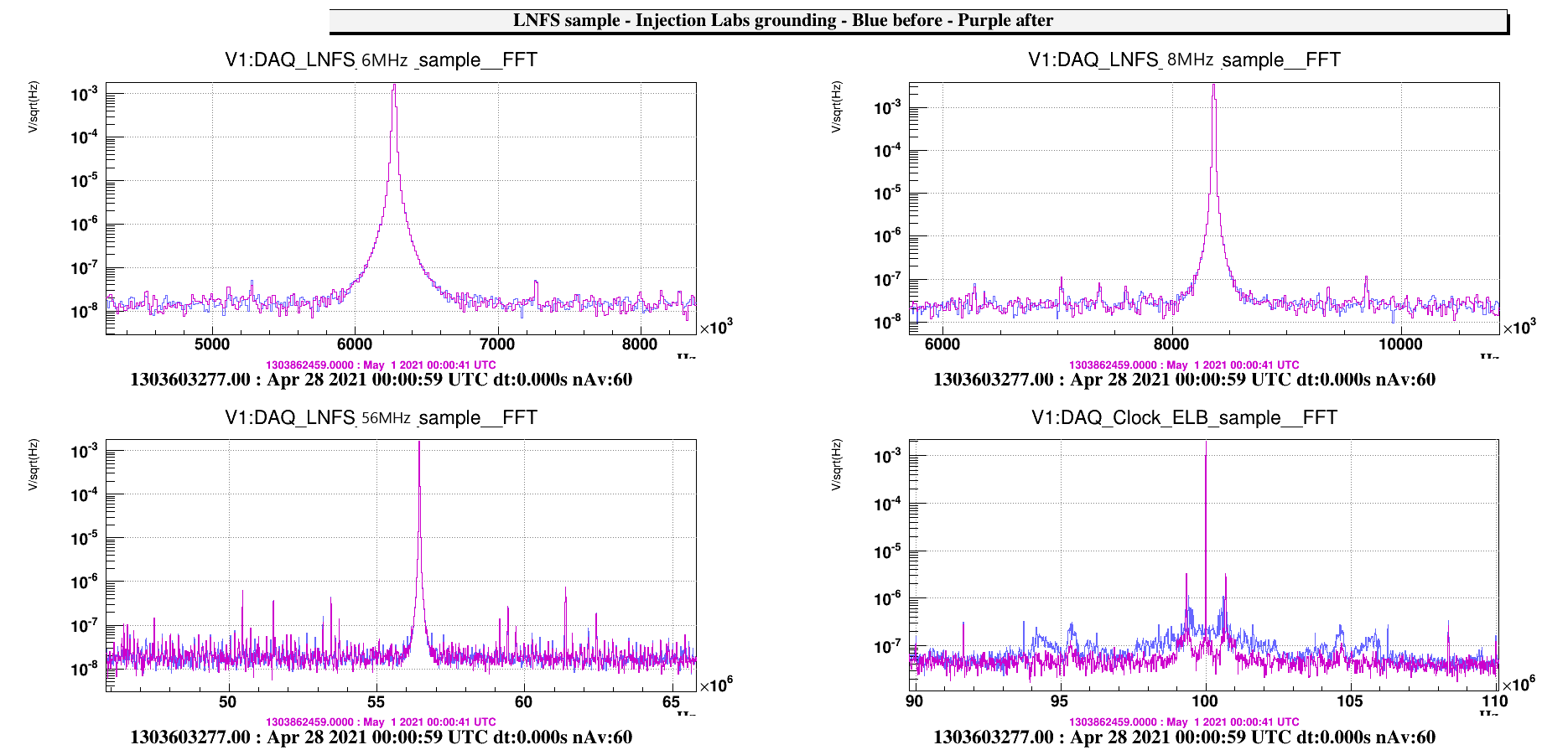
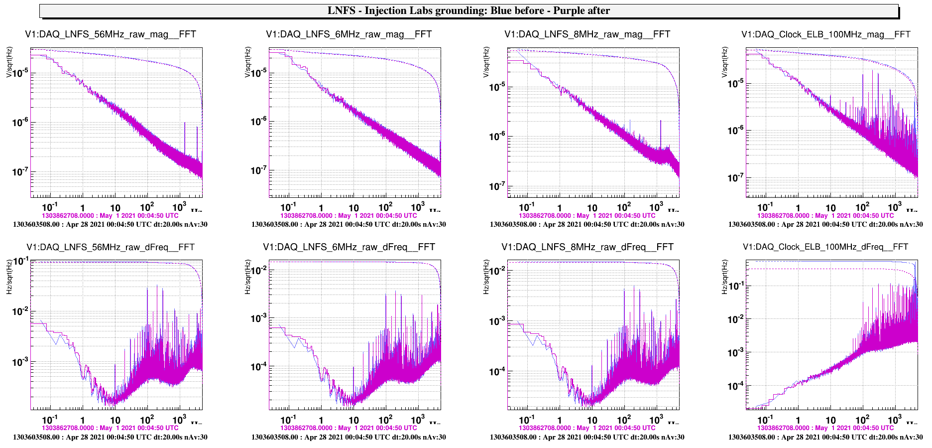
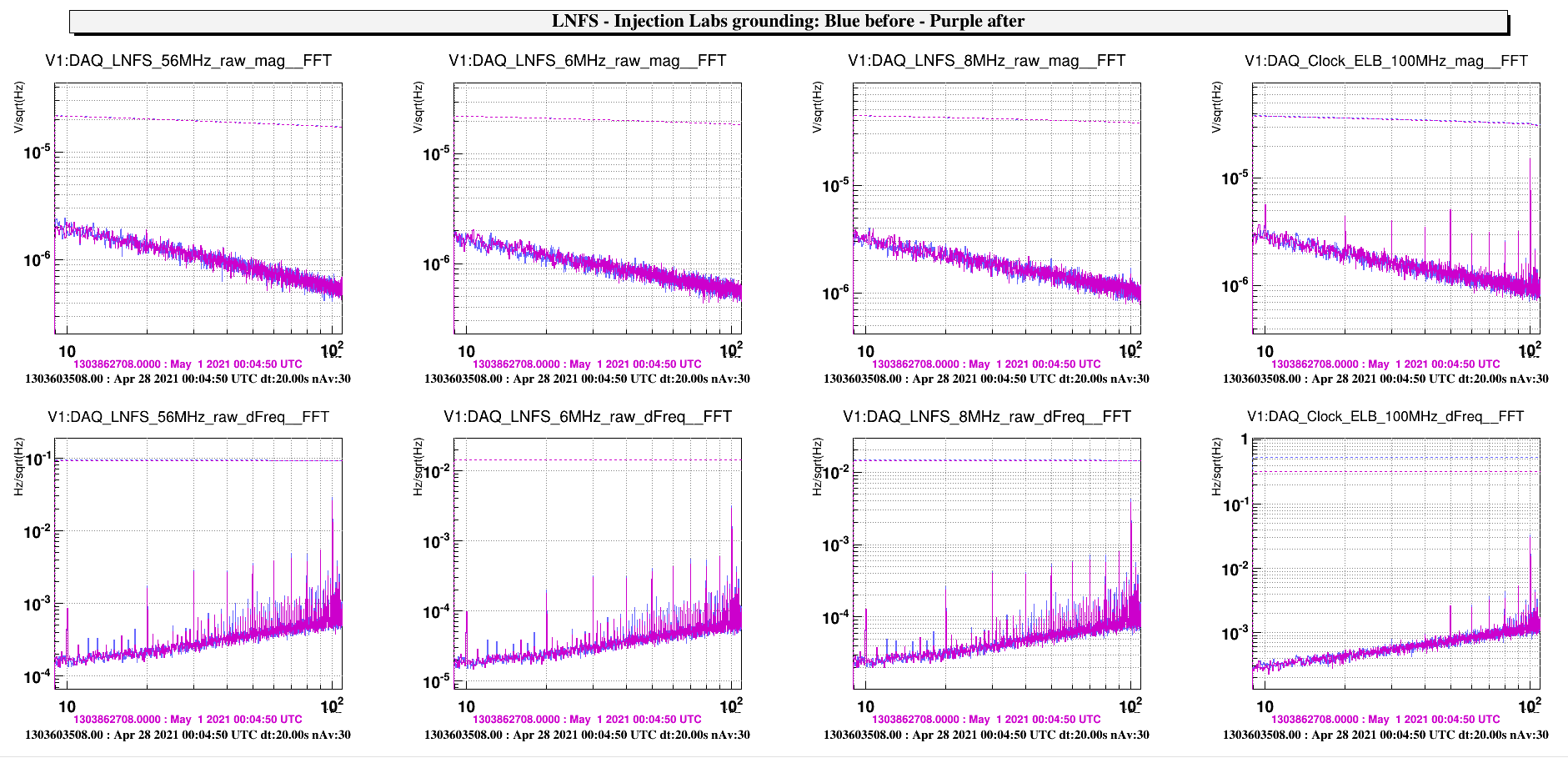
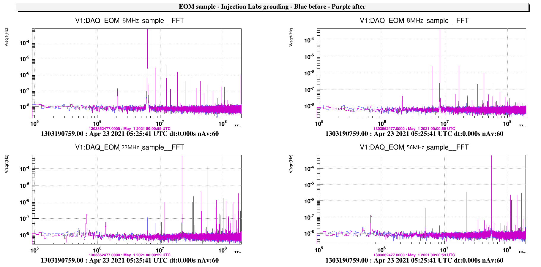
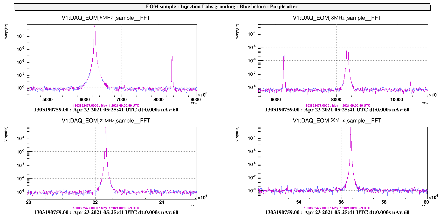
Here the ASD of some channels acquired in the "Piscina": blue for the grounding and purple after
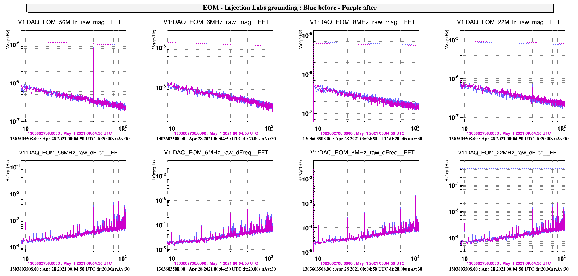
- LNFS 6,8,56MHz and DAQ 100MHz distrribution : sample (zoom), magnitude and frequency noise(dFreq) (zoom)
- in the DAQ 100MHz distribution there is low noise on the sample channel after the grouding, but the line at 0.670MHz is present at its beating around 100MHz seems higher .
- none modification in the LNFS_{6,8,56}MHz magnitudes
- less 1Hz harmonic in the the LNFS_{6,8,56}MHz frequency noises, while the rms of the DAQ 100MHz frequency noise is reduced
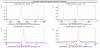
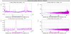
- EOM 6,8,22 and 56MHz: sample (zoom), magnitude and frequency noise(dFreq) (zoom)
- none modification in the EOM_{6,8,22,56}MHz magnitudes
- less 1Hz harmonic in the the EOM_{6,8,56}MHz frequency noises,
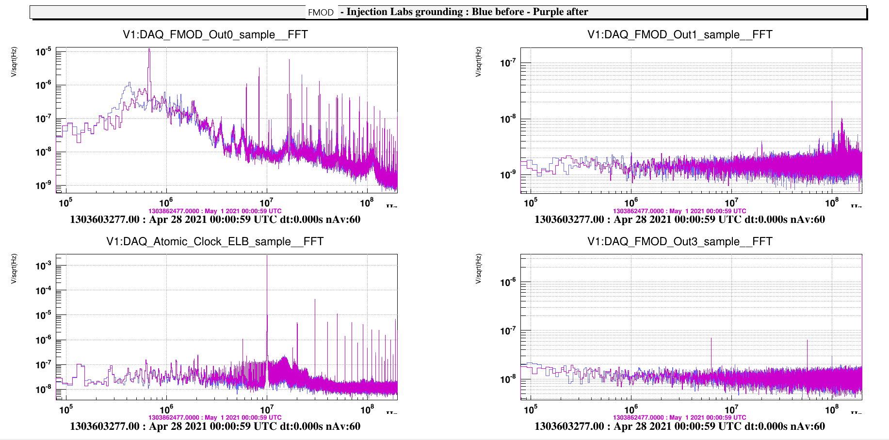
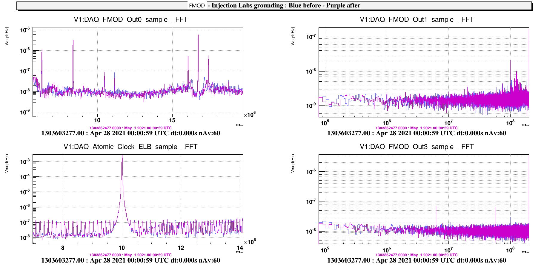
- FMOD and Atomic clock: sample(zoom),
- the line at 0.670Mhz is present and it create a lot of beatiing
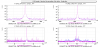
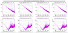
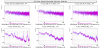
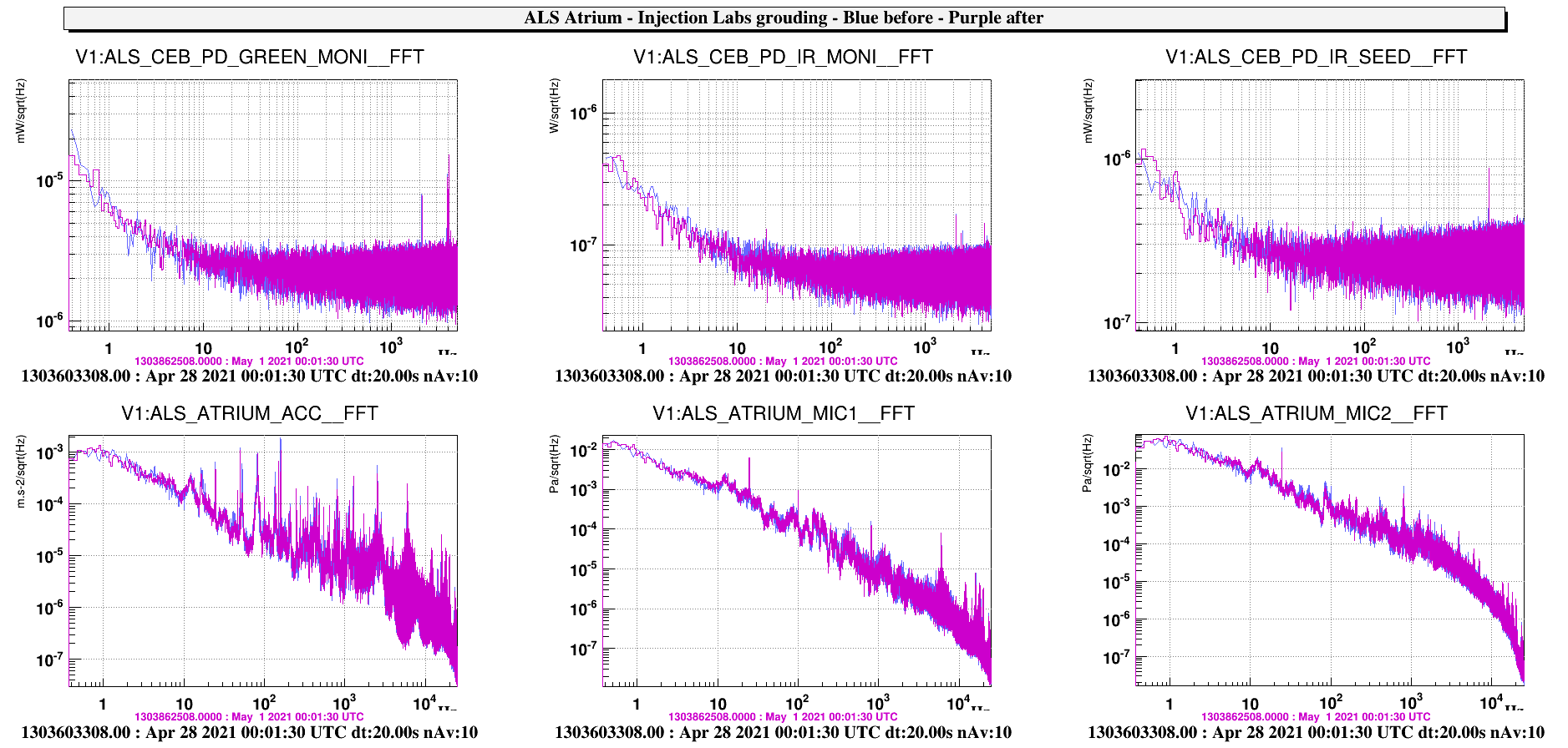
Here (zoom) the ASD of some ALS channels and Environmental channels collected from the Atrium and acquired by a Daq Box in the "piscina": none relevant modification

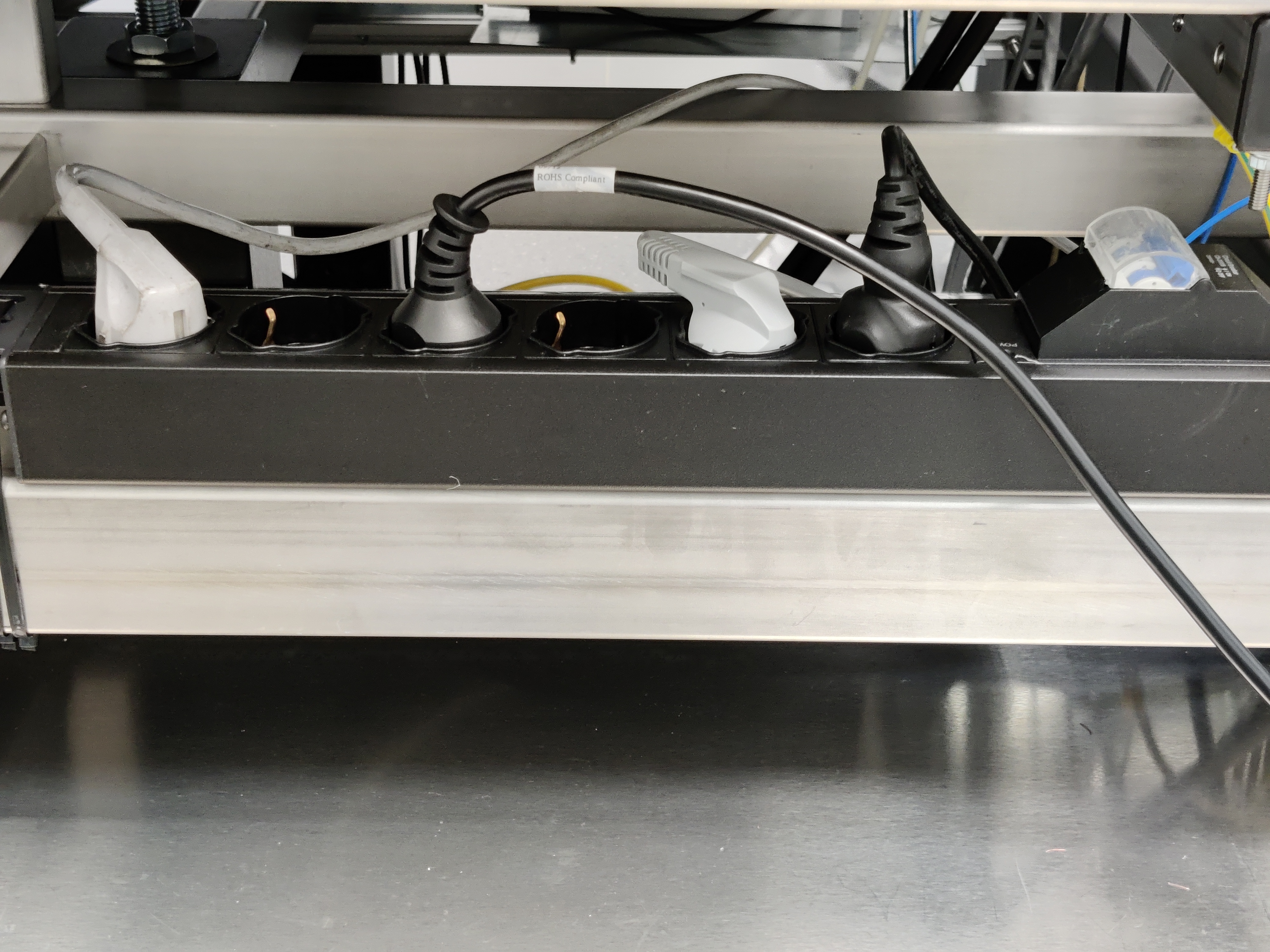
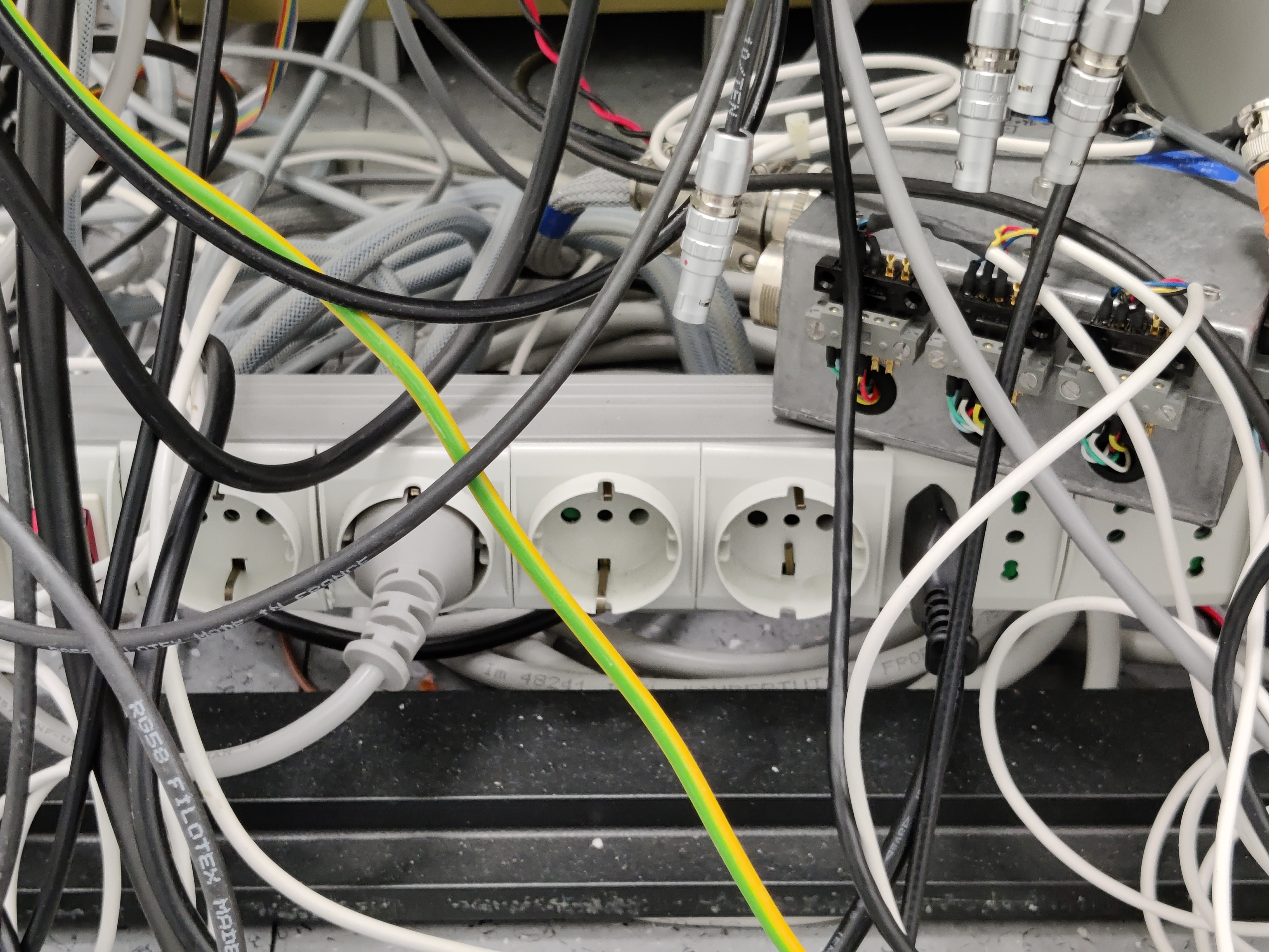
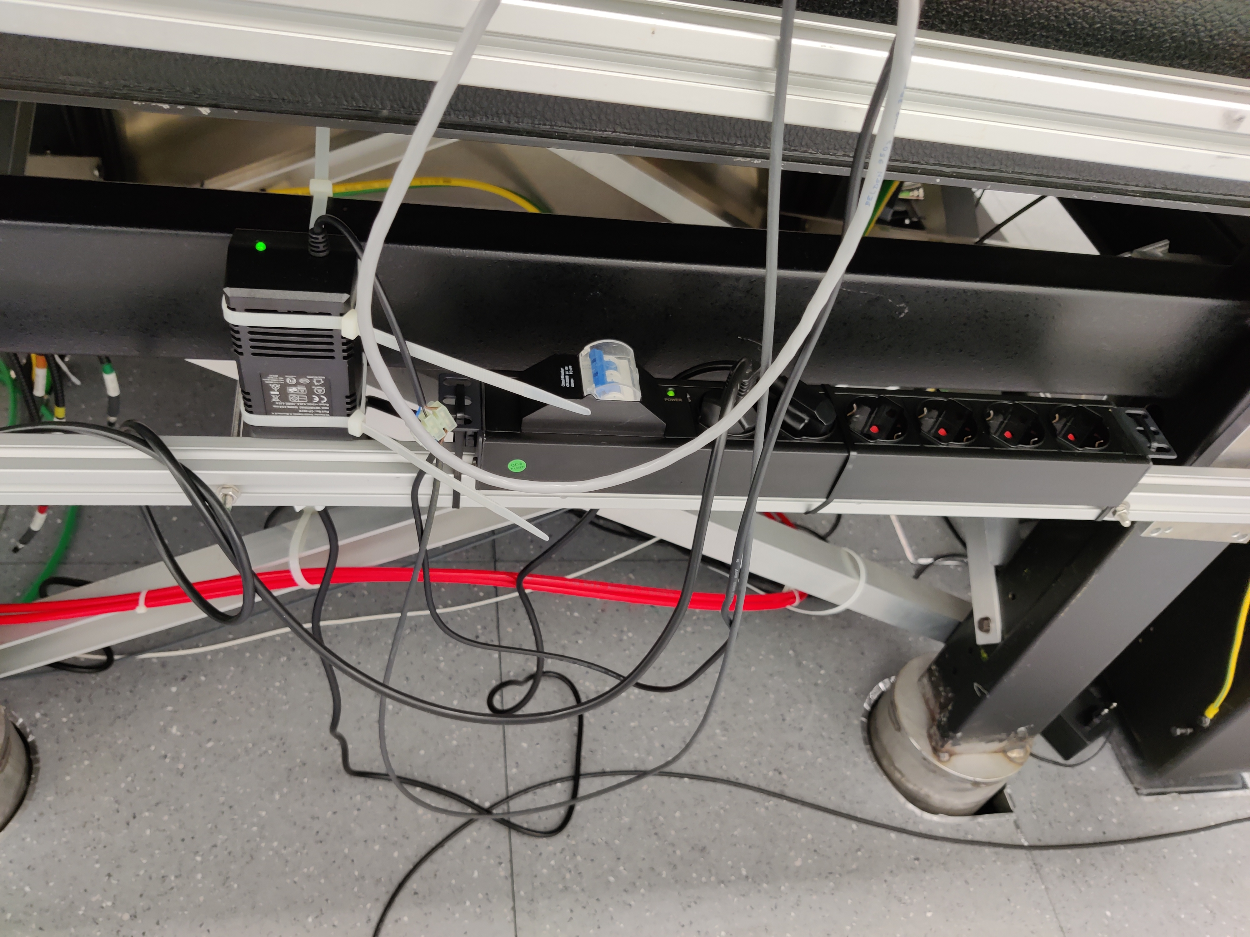
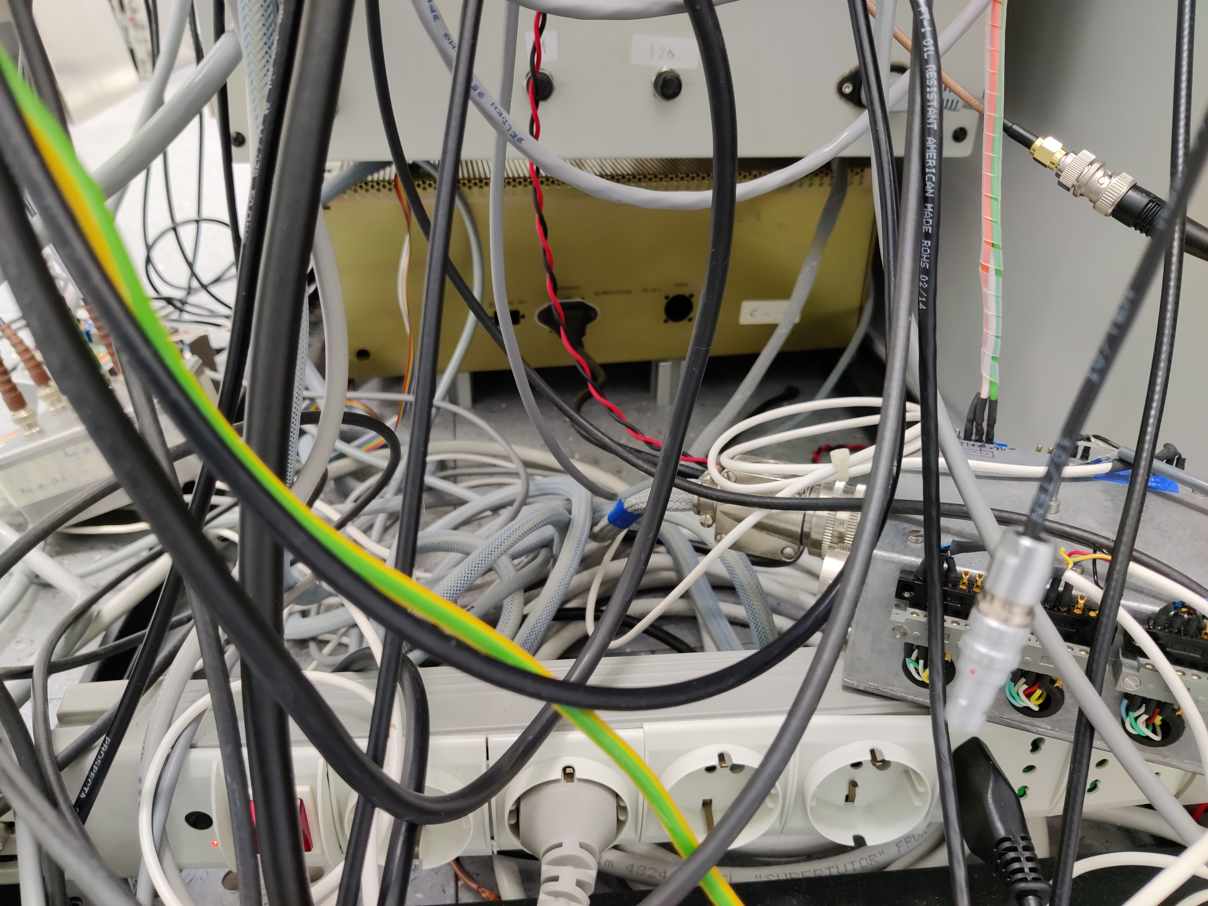
This morning we kept on working on the grounding of the laser lab by unpplugging the different devices that were plugged on the "flying" multi sockets and replugging them on the new ones installed last week. See the attached photos. Here below is the log of our intervention, indicated times are local times.
We had to switched off both the ML and the fiber amplifier. After the changes, everything relocked smoothly.
On Walid Chaibi instructions, we brought the signal PSL_PSL_FIBER_AMP_Pump_Imon_D2 to 2.415 A. It had been set at 2.405 A last week while its normal working point should be 2.415A. New values on the display 77.9 W 5.85A
To be noted that two devices are still connected to the old multi socket on the bottom of the rack: the signal repeateter on top of the rack and an artemis power supply on the bottom (see 3 last pictures). We would like to ask concerned people to know if there are any precautions to be taken before switching those devices off. In particular the artemis power suplpy that supplies many other devices: LB photodiodes, RF amplifiers for EOM and AOM, SL rampeauto...
***
From multi socket on the bottom of the rack to the new multi socket on the rack:
111000 RF generator used for the scan of the PMC
111220 diff2diff box
112600 we put PMC_TRA as a trigger for the pmc instead of IBJM, we relocked the PMC and take a reference for AMP_DC and PMC_TRA
113015 we switched off the fiber amplifier
113500 we switched off the master laser and repplugged it on a new multi socket
114530 switched on master laser
114600 increased current in master laser
114930 reached the nominal values
Unpplugging of the following devices from the multi socket on top of the Faraday cage and repplugging on the new multisocket on the faraday cage (not connected yet):
115000 stabilized power supply for the monitoring of the fiber ampli security
115157 general power supply of the fiber amplifier
115450 artemis power supply that supplies pmc rampeauto and signals of fiber ampli
115510 oscilloscope used for pmc scan
115630 connection of the new multi socket
115646 switched on artemsi power supply for pmc and fiber amp signals
115820 power supply for the pmc monitor photodiodes unplugged and replugged on the new multi socket (right side of LB)
120630 fiber amplifier back to "new nominal" current:
120844 PMC locked
121330 Put back IBJM as a trigger for PMC rampeauto
122045 all PSL/INJ loops are closed
122550 ML noise eater OFF/ON to remove the 680 kHz line
***

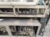
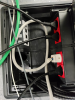

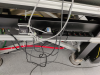
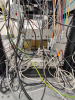
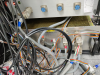
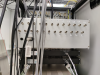
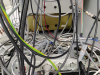
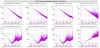
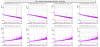
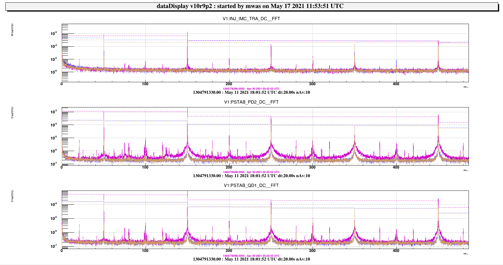
Figure 1 highlights the impact of the electrical grounding work. It shows three times when the input mode cleaner is not locked, with several photodiode channels after the input mode cleaner. So times when there is no or little light on these sensors, and electronic noise is dominant. The purple curve is in the night before the electrical grounding work, and in brown is the night after. This decreased the 50Hz and its harmonics by factor between 2 and 5, depending which sensor we look at. In addition it reduced also the wide shoulders around the 150Hz, 250Hz, etc. There have been some other small improvement in the electrical connection on May 4, but this had no noticeable impact. The blue curve shows data on May 11, which are comparable (slightly higher 50Hz harmonics) than just after the electrical grounding work.
Concerning the two remaining devices:
***
To be noted that two devices are still connected to the old multi socket on the bottom of the rack: the signal repeateter on top of the rack and an artemis power supply on the bottom (see 3 last pictures). We would like to ask concerned people to know if there are any precautions to be taken before switching those devices off. In particular the artemis power suplpy that supplies many other devices: LB photodiodes, RF amplifiers for EOM and AOM, SL rampeauto...
***
Yesterday morning around 9 UTC, we plugged them onto the new multi socket and removed the old flying multi socket.
The only precaution that has been taken to do this operation was to switch off the 14 MHz that is sent towards the EO driver.