At the beginning of the shift, the CH settings were:
-
P_WI = 41 mW
-
P_NI = 15 mW
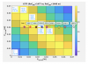
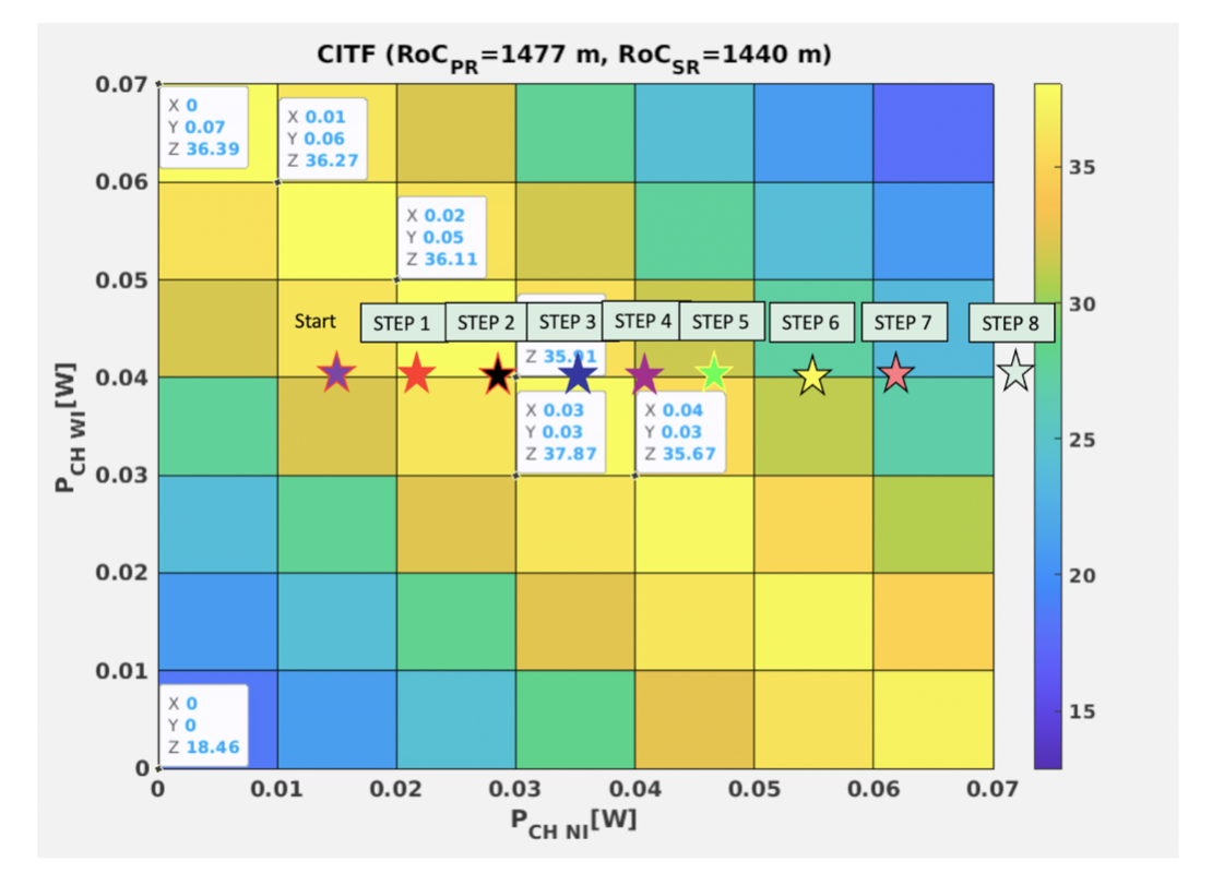
Identified by the pink star labelled “Start” in figure 1. Figure 1 shows the gain of the 56 MHz sideband gain for the CH powers. Thus, according to the simulation, increasing the NI power, while keeping the WI constant, will improve the gain.
Reminder: when the steady state has been reached after each step in the CH power, ISC team checked the alignment.
| Steps | UTC | Power injected in ITF in WI | TCS_WI_CO2_POWER_CH_PICKOFF | Power injected in ITF in NI | TCS_NI_CO2_POWER_CH_PICKOFF |
|---|---|---|---|---|---|
| 1 | 7:47:24 | 41 mW | 0.251 W | 21 mW | 0.14 W |
| 2 | 08:46 | 41 mW | 0.251 W | 29 mW | 0.183 W |
| 3 | 09:24 | 41 mW | 0.251 W | 36 mW | 0.23 W |
| 4 | 10:00 | 41 mW | 0.251 W | 42 mW | 0.265 W |
| 5 | 10:32:26 | 41 mW | 0.251 W | 48 mW | 0.302 W |
| 6 | 11:16 | 41 mW | 0.251 W | 56 mW | 0.356 W |
| 7 | 11:58:36 | 41 mW | 0.251 W | 65 mW | 0.409 W |
| 8 | 12:28:02 | 41 mW | 0.251 W | 74 mW | 0.464 W |
| 9 | 13:40:50 | 41 mW | 0.251 W | 56 mW | 0.356 W |
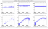
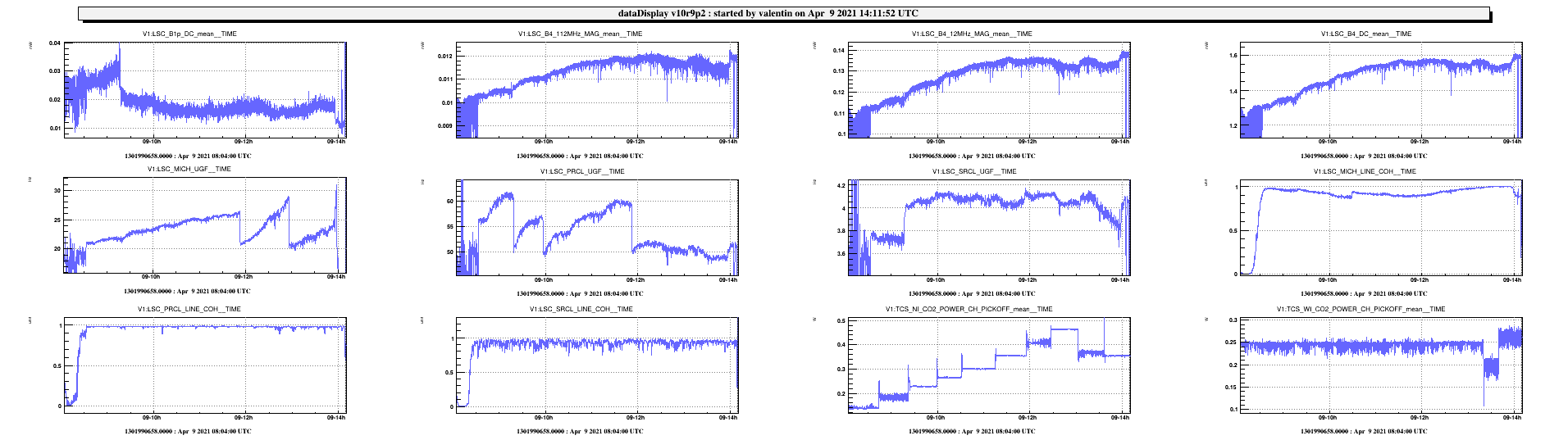
After step 8, we observed a decrease of the sidebands’ absolute values and hence, at 13.40:50 UTC, we came back to the value set at step 6 (see figure 2).
We left the CH in the following configuration:
-
P_WI = 41 mW
-
P_NI = 56 mW
To be sure to be sitting on the maximum of the sidebands power, the equivalent scan for the WI CH should be done.