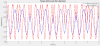
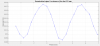
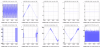
1. to check the coarse alignment of LO and CC, we send a phase modulation on HD M4_Z (f=0.5Hz, ampl=0.5V) to optimize the fringes (SQZ_EQB1_HD_DIFF_RF_4MHz_I) by tuning the angular d.o.f. of the M4 and M6 mirrors in front of the HD. We obtain Fig. 1.
2. We closed the slow CC loop and observing SQZ_EQB1_HD_DIFF_RF_4MHz_mag , we have further maximized the magnitude by tuning the CC phase=1.1 rad.
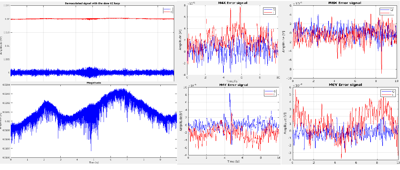
2. We applied dither lines to AA actuators (M4_X, M4_Y, M6_X, M6_Y) with well separated frequencies and in a frequency range with less noise: 412Hz, 512Hz, 612 Hz, 712Hz. For M4 we applied dither lines with ampl=0.02V, for M6 ampl=0.005V.
3. Observing demodulated signals, i.e. the I and Q quadratures of the angular d.o.f of the M4 and M6, we applied linear ramps to one d.o.f. at a time and we tuned the demodulation phase in order to minimize the corresponding ramp on the Q quadrature (process EQB1_HD_AA_dither between lines 14-19):
HD_M4_X_phi0 3.62
HD_M4_Y_phi0 4.65
HD_M6_X_phi0 5.6
HD_M6_Y_phi0 1.60
We then set the bias to one d.o.f. at a time corresponding to the maximization of the magnitude (process EQB1_HD_AA between lines 78-86):
HD_M4_X_ramp 0.5
HD_M4_Y_ramp 2.2
HD_M6_X_ramp 1.4
HD_M6_Y_ramp 2.8
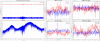
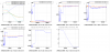
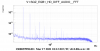
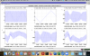
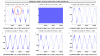
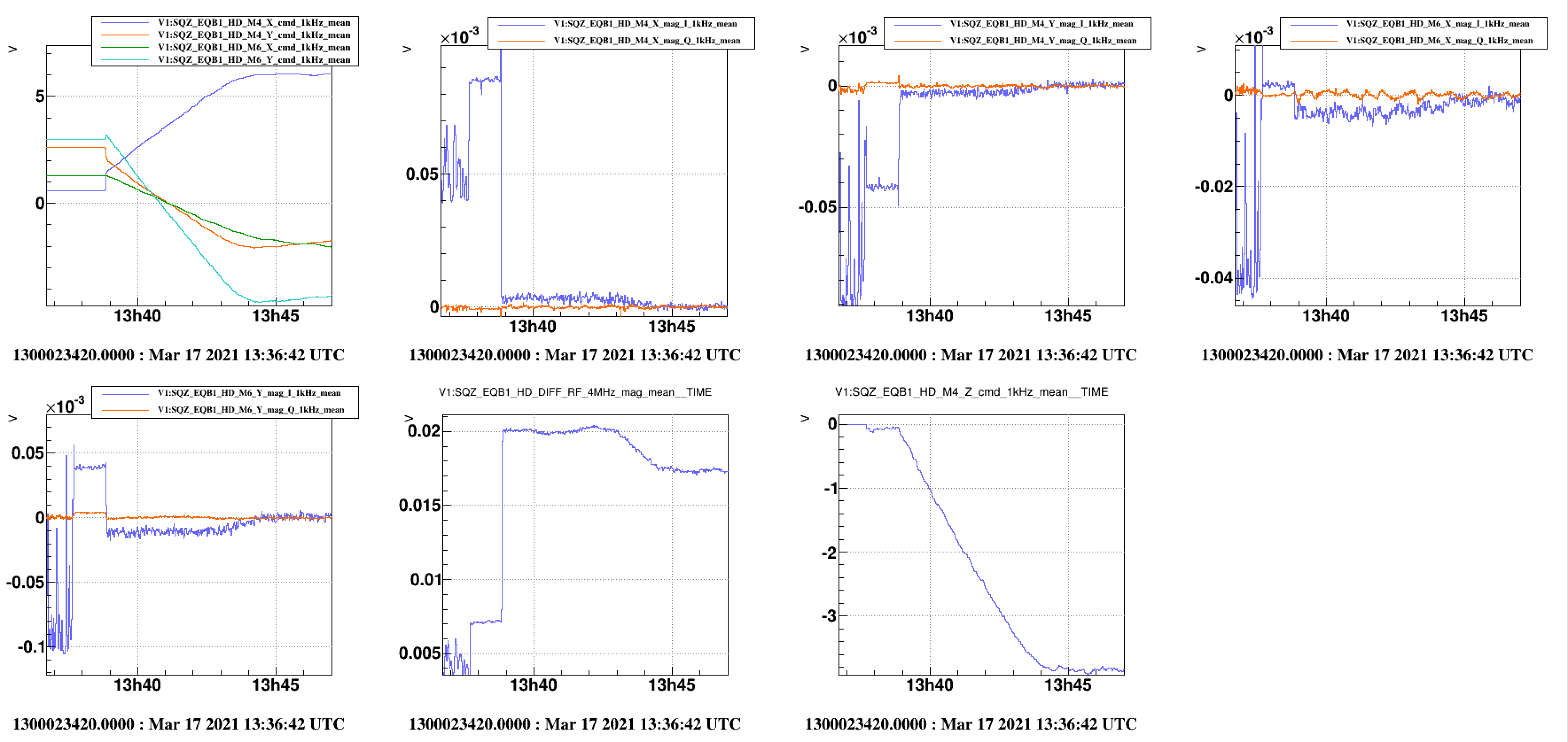
4. We closed the HD dither AA loop to maximize the amplitude of the beat note, at first one d.o.f. of mirrors at a time and to do this we set up a diagonal driving matrix to apply feedback signals, we set up a simple loop filter with a demodulation filter at 5Hz, pole at 0Hz and a frequency roll-off at 10 Hz. Then we tuned the proportional gain, the sign and we closed the loop for all 4 d.o.f. with the slow CC loop (G=300), as you can see in Fig. 2. In Fig. 3, where we first closed the slow CC and then the AA loop, we see in particular that the phase actuator, SQZ_EQB1_HD_M4_Z, moves when we close the angular loop. In the end, however, all the actuators stabilize, so we can keep the two loops closed at the same time.
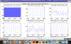
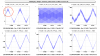
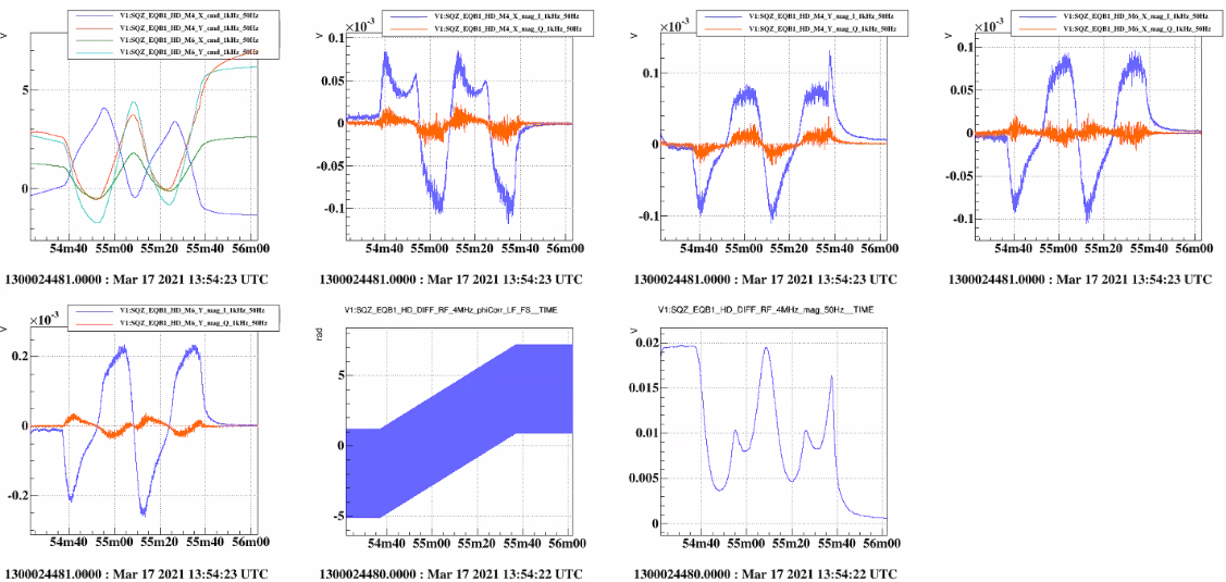
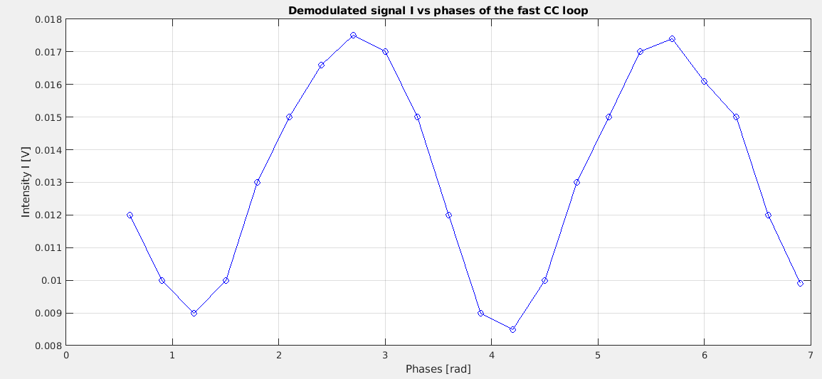
5. To check the interplay between AA and CC loops, we closed AA loop with the slow CC loop with 2π phase scan (Fig. 4) and then we tried to do the same with Fast CC loop. However, doing a 2π phase scan, we did not find a fixed gain value for the fast CC loop to remain closed. We have plotted the intensity of the demodulated signal I as a function of the phases of the fast CC (G=10000) (Fig. 5). The optical gain during a phase scan varies by a factor of 2 so this must be compensated by the gain of the CC loop. Using the calibration done, a python script will probably be prepared that will do a phase scan by compensating for gain.
In conclusion, we managed to engage the AA loop with dither lines reliably. Further analysis is ongoing to better characterise the loop performance. Further investigation will be needed for:
- better understanding of the interplay with CC loop and CC phase
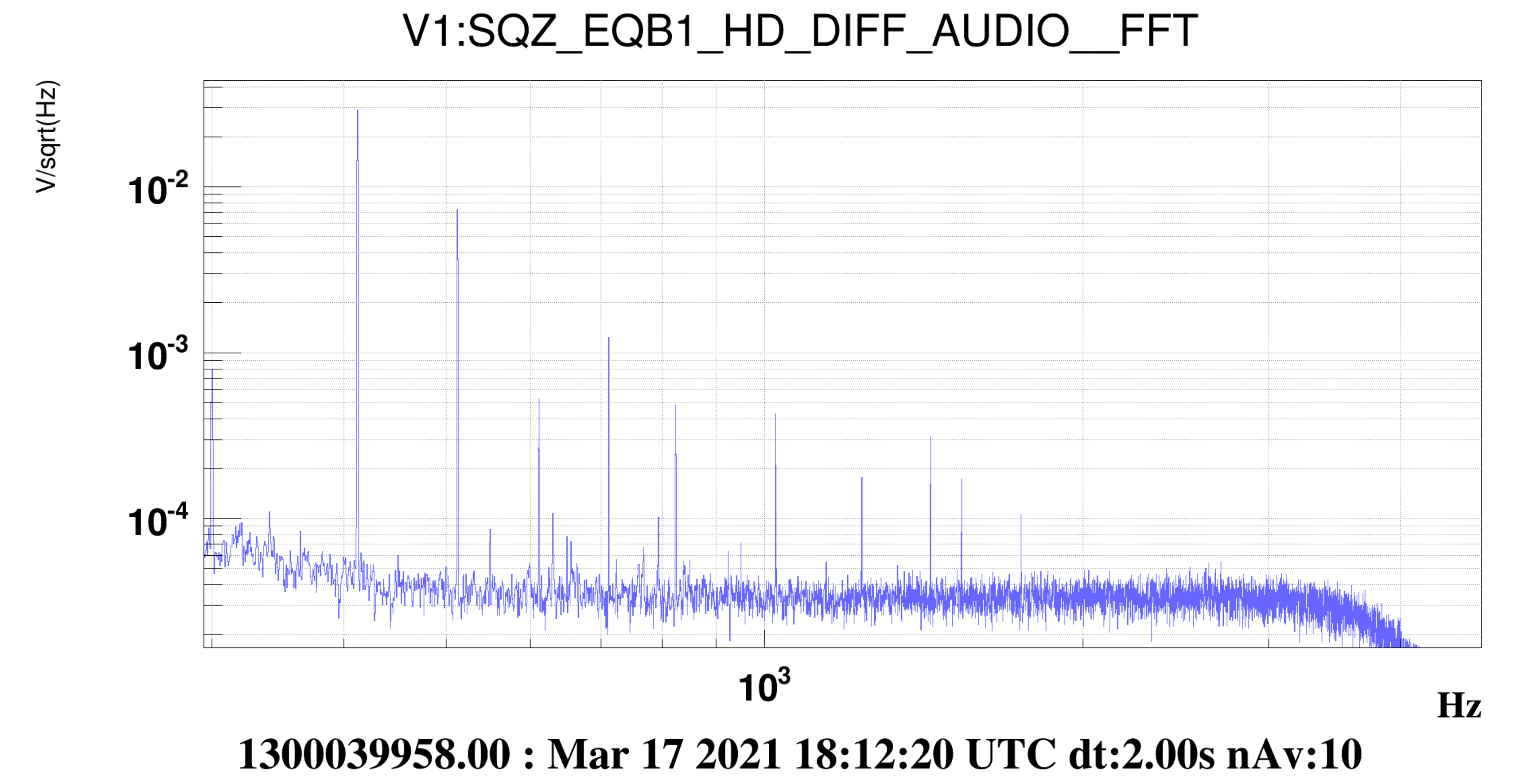
- optimisation of dither lines amplitude and frequency (the currently applied dither lines are shown in Fig.6)
- an improvement in the AA loop logic
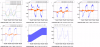
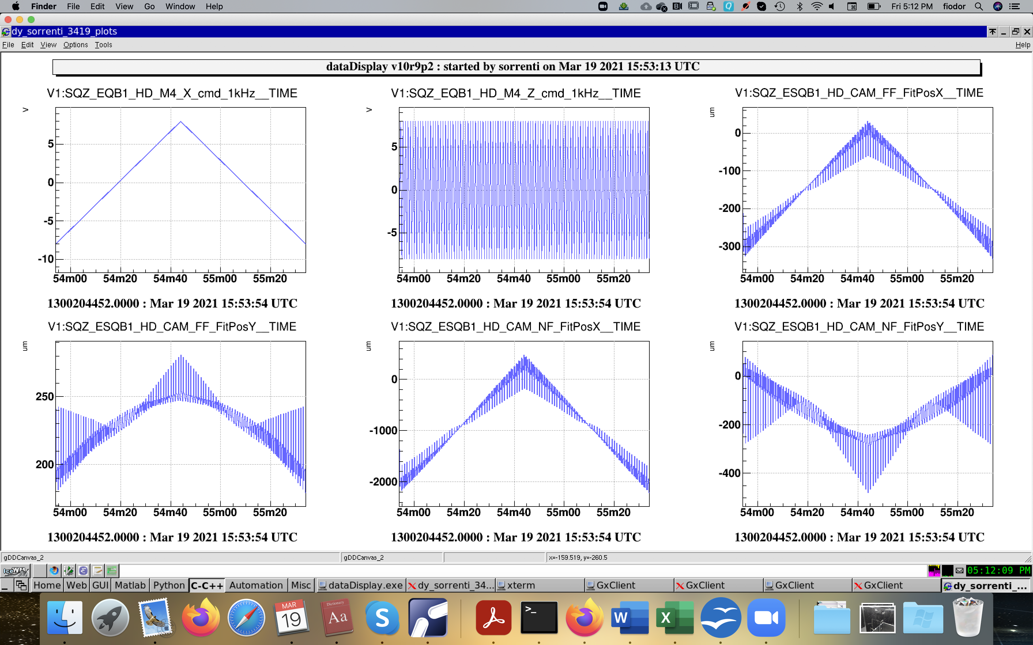
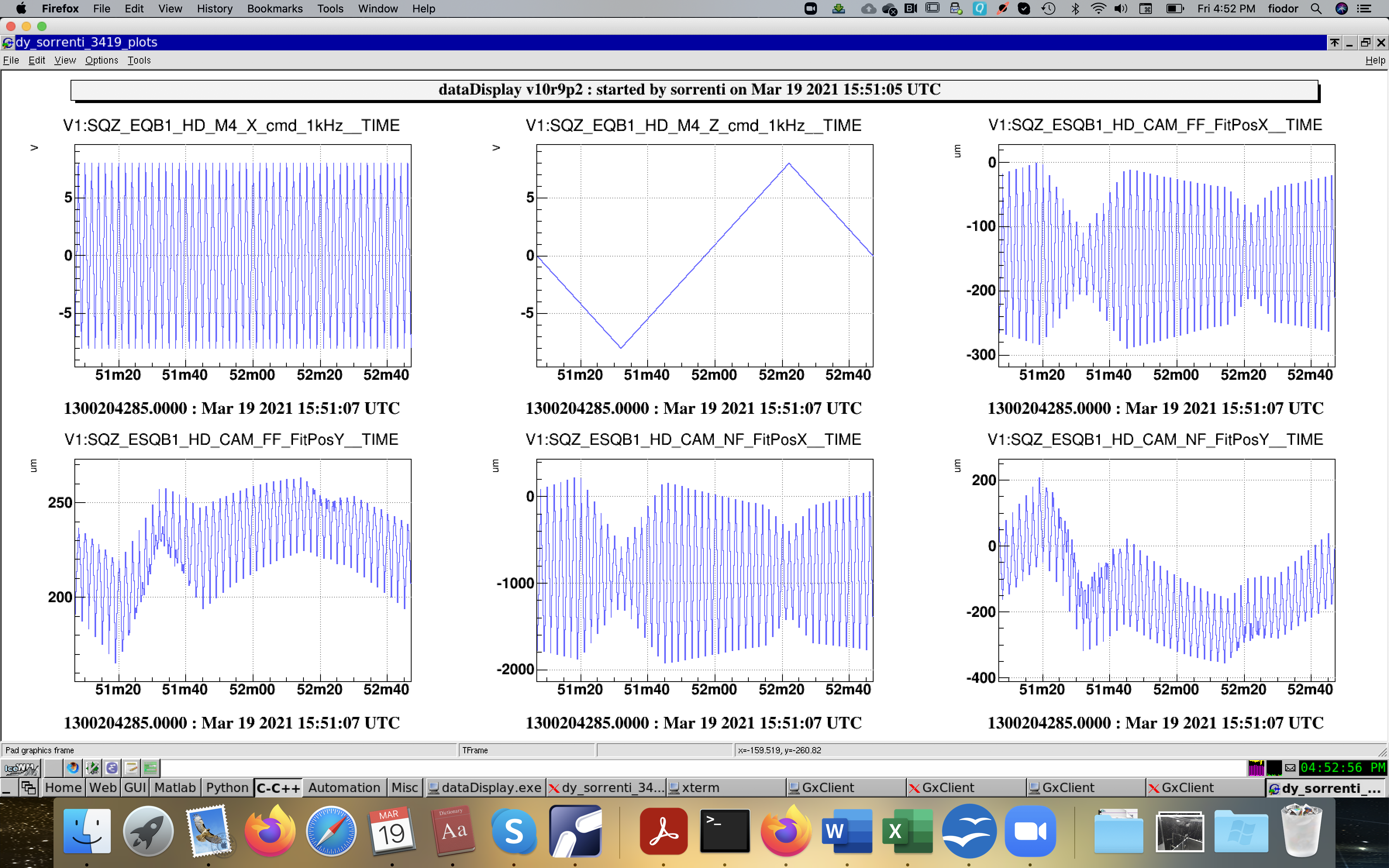
The interplay of slow CC loop and AA loop depends on the parallel-kinematics design of the 3-axial actuator, i.e. mod. S-325.30L from PI. The tip-tilt motion is not independent on the axial motion. In the attached plots a test with HD cameras monitoring the position of LO beam while moving the M4 mirror along the horizontal tilt angle (M4_x) and along the axial position (M4_Z). In the first plot, we apply a slow ramp on M4_X and a fast modulation on M4_Z. In the second plot, we apply a slow ramp on M4_Z and a fast modulation on M4_X.
The axial modulation induces an angular modulation which is seen on the position of the beam on the cameras. The horizontal modulation is only null when the horizontal angular position of the actuator is centered to zero. The vertical modulation is never zero during the test, as the vertical angular position (M4_Y) was not centered to zero.
In principle the effect of axial motion on angular position can be canceled by properly combining the M4_Z command with the M4_X and M4_Y commands, provided that the calibration given by the first plot is constant with time.
This effect is absent with the actuator of the fast CC, ie. S-303.CD from PI. See third attachment, where the axial modulation only induces a tiny horizontal displacement as expected on a mirror at 45 deg incidence.

The same for the new HD_M4_Y_cmd.
ACL_SUM_CH HD_M4_X_cmd "" 1 1. HD_M4_X_nc 0. HD_M4_XZ
ACL_SUM_CH HD_M4_Y_cmd "" 1 1. HD_M4_Y_nc 0. HD_M4_YZ
As you can see in Figure, we applied a slow ramp on M4_X (f=0.005Hz, ampl=12V, bias=-6V) and a fast modulation on M4_Z(f=0.5Hz, ampl=12V, bias=-6V). In particular, you can see the effects of the correction in the NF cameras before 15:37UTC, and after without correction. The plots relating to the CAM_FF are not significant as we had the beams cut in that camera.
To have the optimal correction, we tuned the coefficient of HD_M4_XZ and we obtained the optimal correction with a weight of 0.03.
We then verified that this correction worked for M4_Y and that it was also optimal with the same correction coefficient.
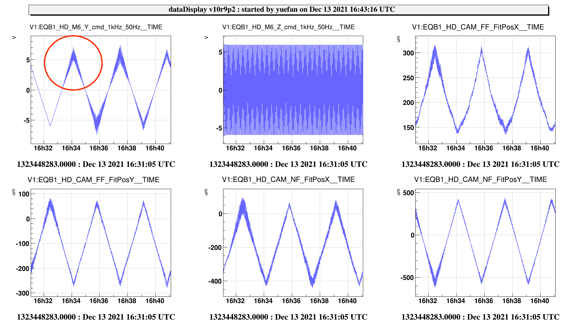
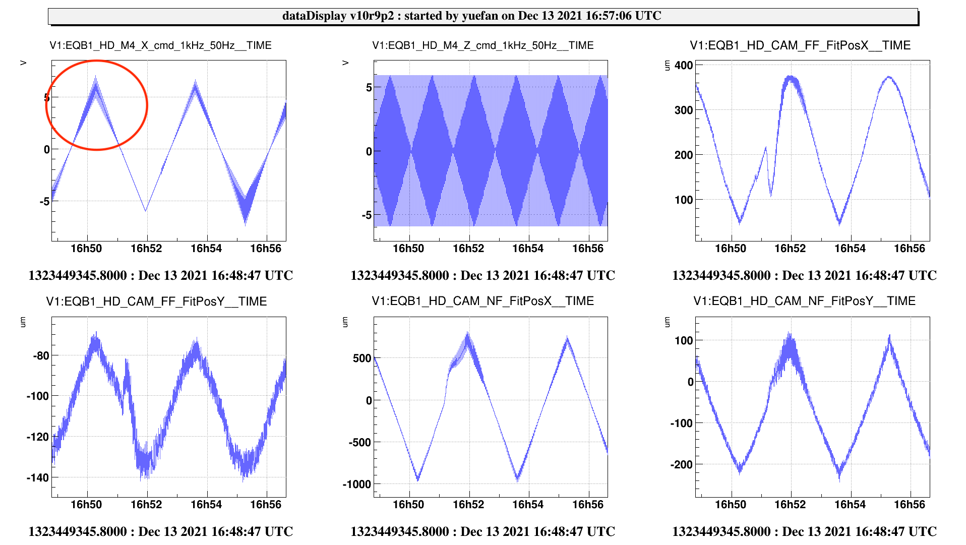
Since the work mentioned in the previous entry was only done to the M4, today we performed the same procedure also to the HD M6 mirror.
First we added the following lines to the config file:
ACL_SUM_CH HD_M6_X_nc "" 1 1. HD_M6_X_CORR 1. HD_M6_X_ramp 0.00 HD_M6_X_line
ACL_SUM_CH HD_M6_Y_nc "" 1 1. HD_M6_Y_CORR 1. HD_M6_Y_ramp 0.000 HD_M6_Y_line
ACL_OP_CH HD_M6_XZ "" prod HD_M6_X_nc HD_M6_Z_cmd
ACL_OP_CH HD_M6_YZ "" prod HD_M6_Y_nc HD_M6_Z_cmd
ACL_SUM_CH HD_M6_X_cmd "" 1 1. HD_M6_X_nc 0. HD_M6_XZ
ACL_SUM_CH HD_M6_Y_cmd "" 1 1. HD_M6_Y_nc 0. HD_M6_YZ
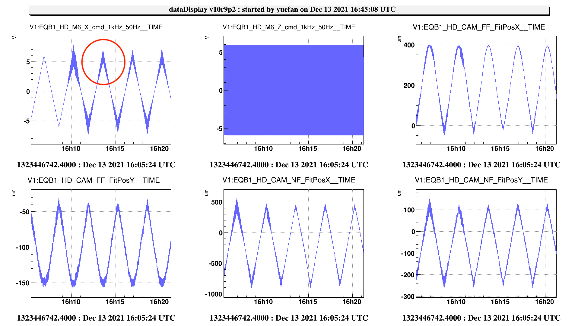
By sending ramps to X(Y) : freq 0.005Hz amp 12V and Z: freq 0.5Hz amp 12V, we checked the signal in the HD FF and NF cameras fitPosX and fitPosY channels for the real movement of the beam.
Then we changed the coefficients in front of the HD_M6_X(Y)Z, we tried to find the value where the coupling between the angular motion and axial motion is minimal. In Fig 1 and 2, we circled out the point where we found the best condition, the coefficients for M6 X and Y are both 0.03.
Just to be sure, we checked again the M4, and the best condition also seems to be 0.03 for both X and Y. (Fig 3 and 4)

