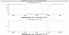
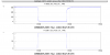
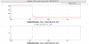
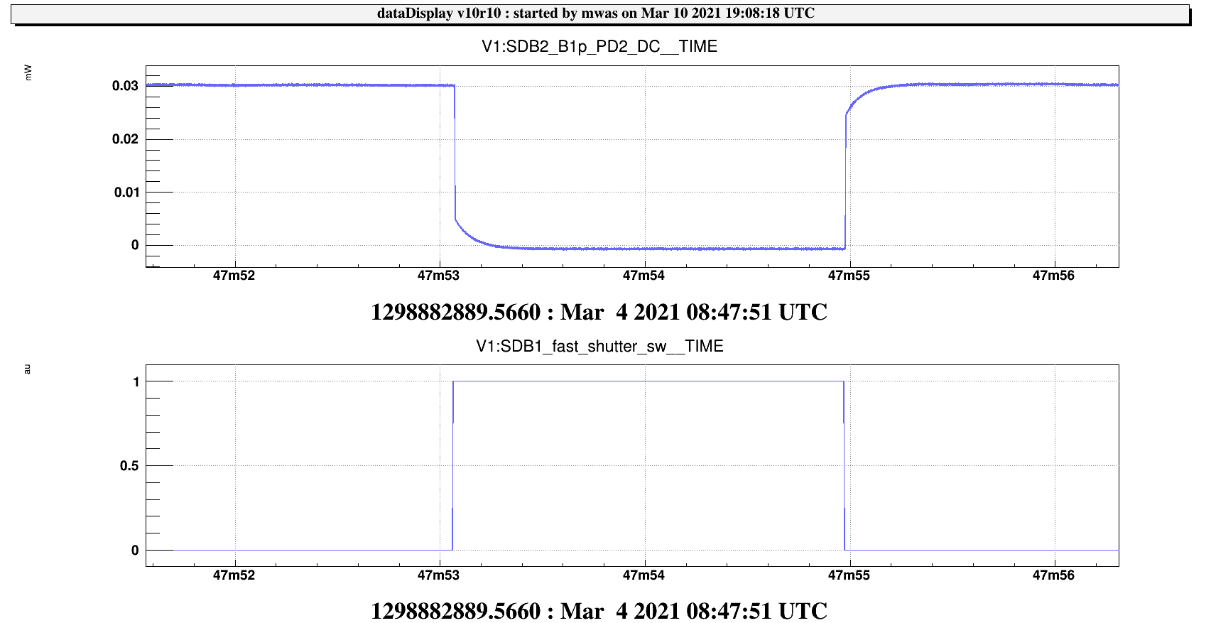
Last week during the shift on the OMC lock we triggered the fast shutter on SDB1 twice by passing through the resonance with the B1 PD1/PD2 shutters open.
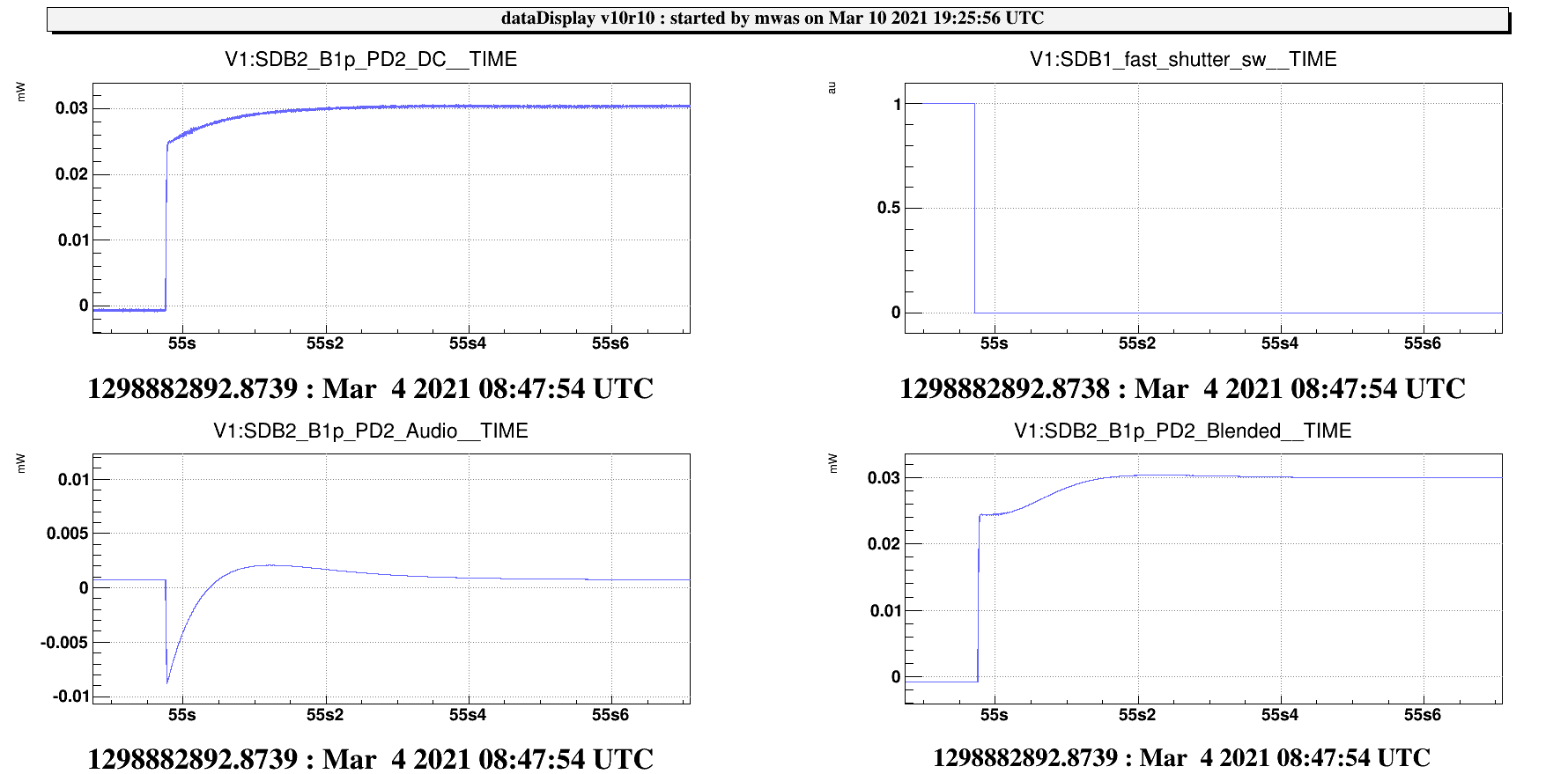
Figure 1 and 2 shows these two occurences. On B1p PD2 we can see that the shutter closure causes a step and then an exponential decay. This is due to the frequency dependent response of the DC channel of the photodiode, that has a pair of simple pole/zero around 2 Hz.
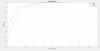
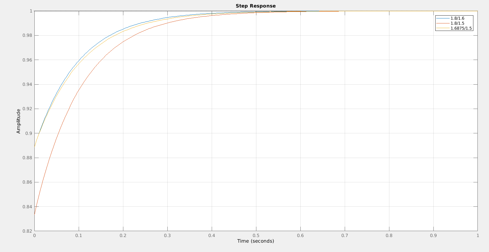
Figure 3 shows a computation of the step response of a pair of pole zeros. In particular the start of the exponential decay corresponds to the ratio of the pole and zero frequency. I expect the time scale of the decay is some average (arithmetic, harmonic, ..?) of the two frequencies. The ratio of the pole and zero frequency is useful to calibrate the PD response above 10Hz relative to the PD response at 0Hz, for example to compute RIN. This is an information that we did know how to measure once the photodiode is installed.
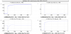
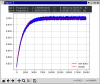
Figure 4 is a zoom of one of the shutter closures. It shows in particular that the power on the PD is sufficiently small that the Audio channel does not saturate, which is a good thing as that could perturb also the DC channel response. It also shows that the blending is not very good, as the blended channel response is quite distorted. The ratio between the start and end of the exponential decay is approximately 0.025/0.03 = 0.833
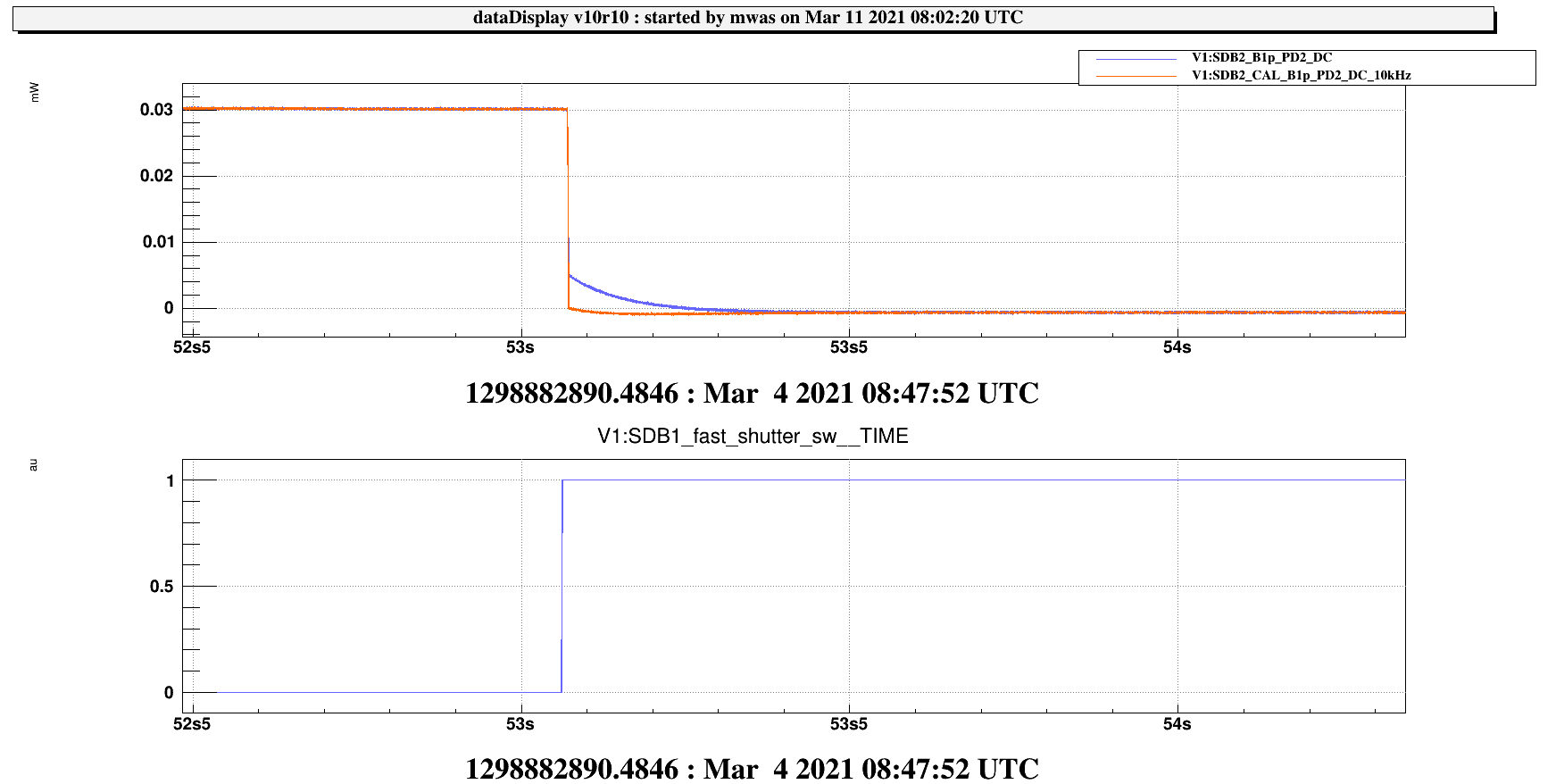
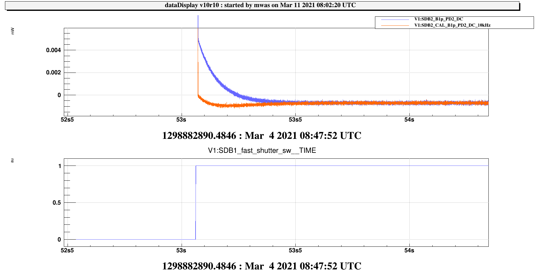
In addition to the photodiode DC channel, there is a channel where the CAL team has corrected the DC response using a zero at 1.5700Hz and pole at 1.8857Hz.
Figure 5 and 6 shows the DC channel and the corrected DC channel. For the CAL corrected channel the remaining step is much smaller, and there is a little bit of an overshoot in the exponential decay transient. The step means that the ratio of the pole/zero frequency is not exactly right, and the overshoot is probably a sign that the average frequency is not exactly fitted either.
