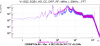
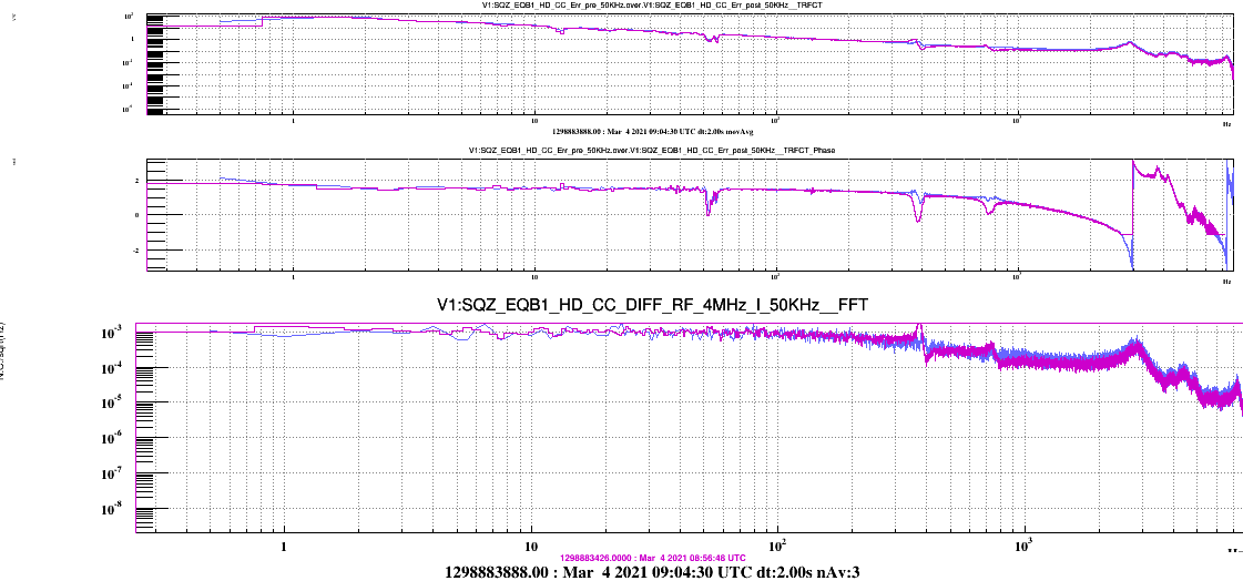
-On march 4 at about 9:55 UTC with the help of Alain, we activated the digital noise correction of CC. The noise between 100Hz and 1kHz decreased as it is visible in Fig.1. The digital noise is probably caused by the integrator thus in the future will be better to move the integrator in the Coarse CC loop (HD_M4_Z) and to use the FAST CC loop to act on higher frequencies fluctuations.
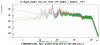
We then studied the behaviour of the CC error signal (SQZ_EQB1_HD_CC_DIFF_RF_4MHz_I_50kHz) by varying the loop gain in order to observe when an oscillation appears. In Fig. 2 for example the purple curve refers to gain about 150, the green curve to G = 700 in which an increase in noise at high frequencies is observed.
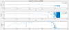
Then, we measured the CC OLG by injecting white noise (Fig.4) with amplitude=0.0007V and G=700: with this noise injection we had a good coherence between 60 Hz and 5kHz. We found three structures that could be problematic: one at 392Hz, one at 784Hz and one at about 1.8kHz. The highest one seems to be a resonance of the mechanics that seems to be difficult to compensate adding zeros and poles in the controller. The one at 392Hz seems to be a resonance of the system not in the controlled degree of freedom. We roughly fitted it in matlab and we found that it is composed by a zero at 392Hz Q=21 and a pole at 375Hz Q=21. The resonance at 784 Hz seems to be the second harmonic of the previous one. We roughly fitted it with a zero at 784 Hz Q=10 and a pole at 750Hz Q=10. Up to now we did not fit the 1.8 kHz structure.
We found that increasing the CC loop gain the 392Hz structure is excited thus we tried to compensate it in the controller.
We tried the following controller:
ACL_FILTER_SET "CC_flt_base" 1 1.0 1.0 20
ACL_FILTER_POLES "CC_flt_base" 0 0
ACL_FILTER_POLES "CC_flt_base" 392 21
ACL_FILTER_ZEROS "CC_flt_base" 375 21
ACL_FILTER_POLES "CC_flt_base" 784 10
ACL_FILTER_ZEROS "CC_flt_base" 750 10
ACL_FILTER_POLES "CC_flt_base" 20000 1
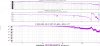
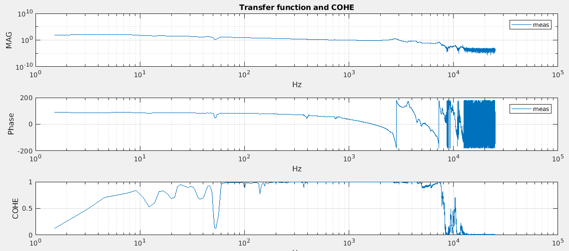
Fig 3. shows the transfer function with and without the phase compensation (G=150).
We then increased the loop gain in order to have a UGF about 1kHz.
Next steps: try to add a low frequency boost in order to suppress low frequency fluctuations, split the control in two actuators: this one used to suppress high frequency phase fluctiations and LO_M4_Z to suppress low frequency fluctuations.