Reports 1-1 of 1 Clear search Modify search
AdV-INJ (Input Power Control (IPC) system)
chiummo, derossi, gosselin, magazzu, melo, spinicelli - 16:46 Monday 22 February 2021 (50848) Print this report
ITF injected power adjustment

Today we decreased the power injected to the interferometer.

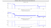
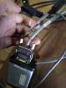
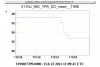
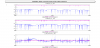
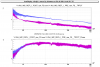
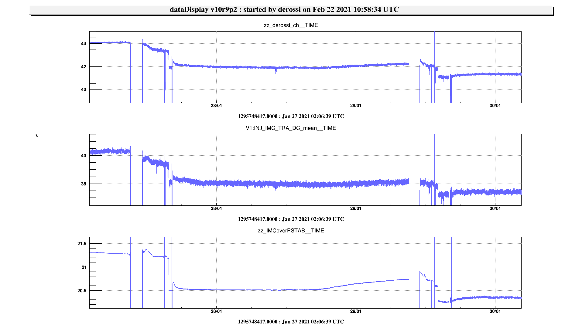
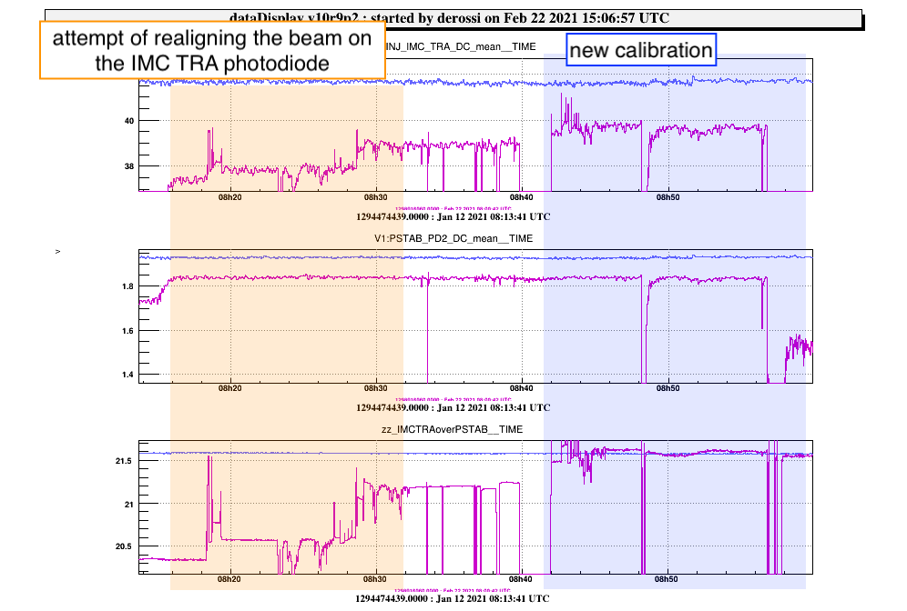
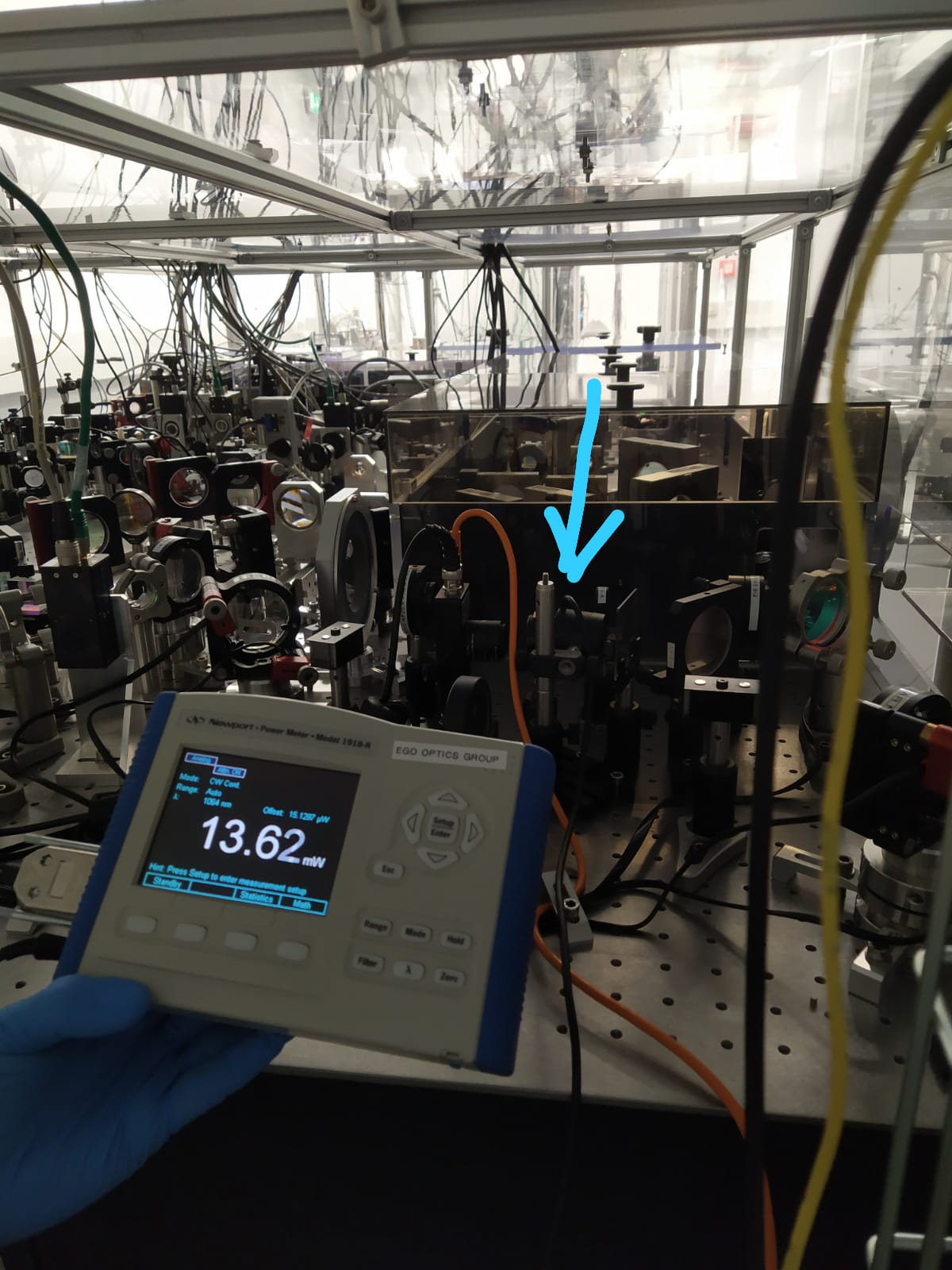
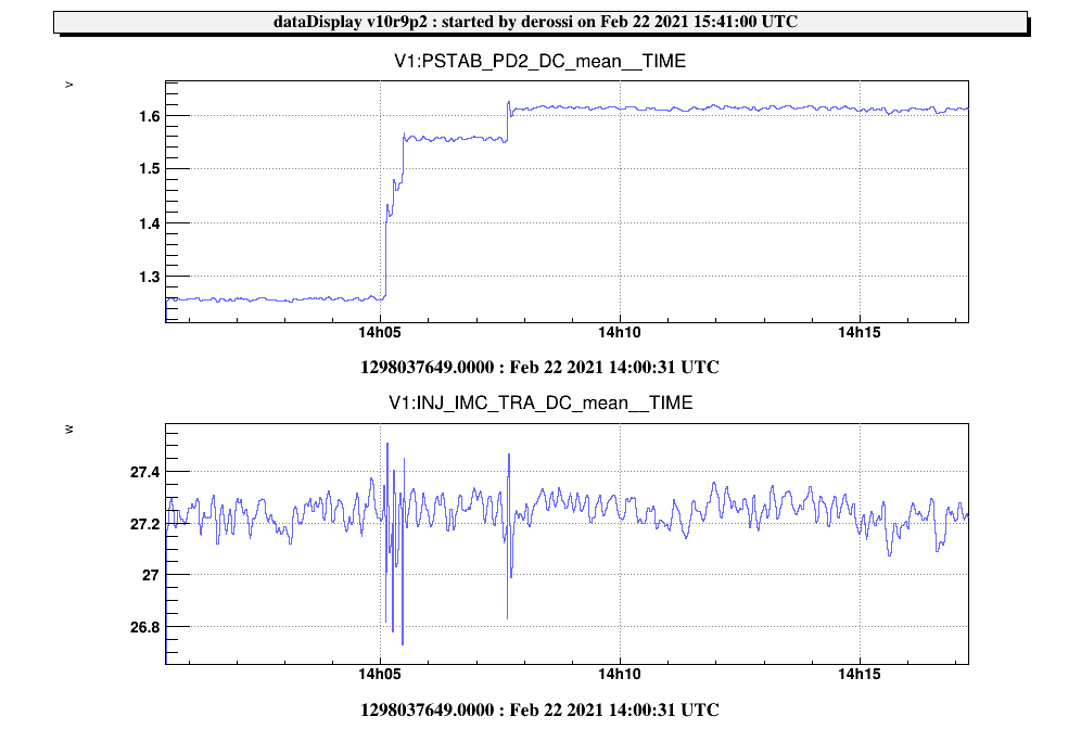
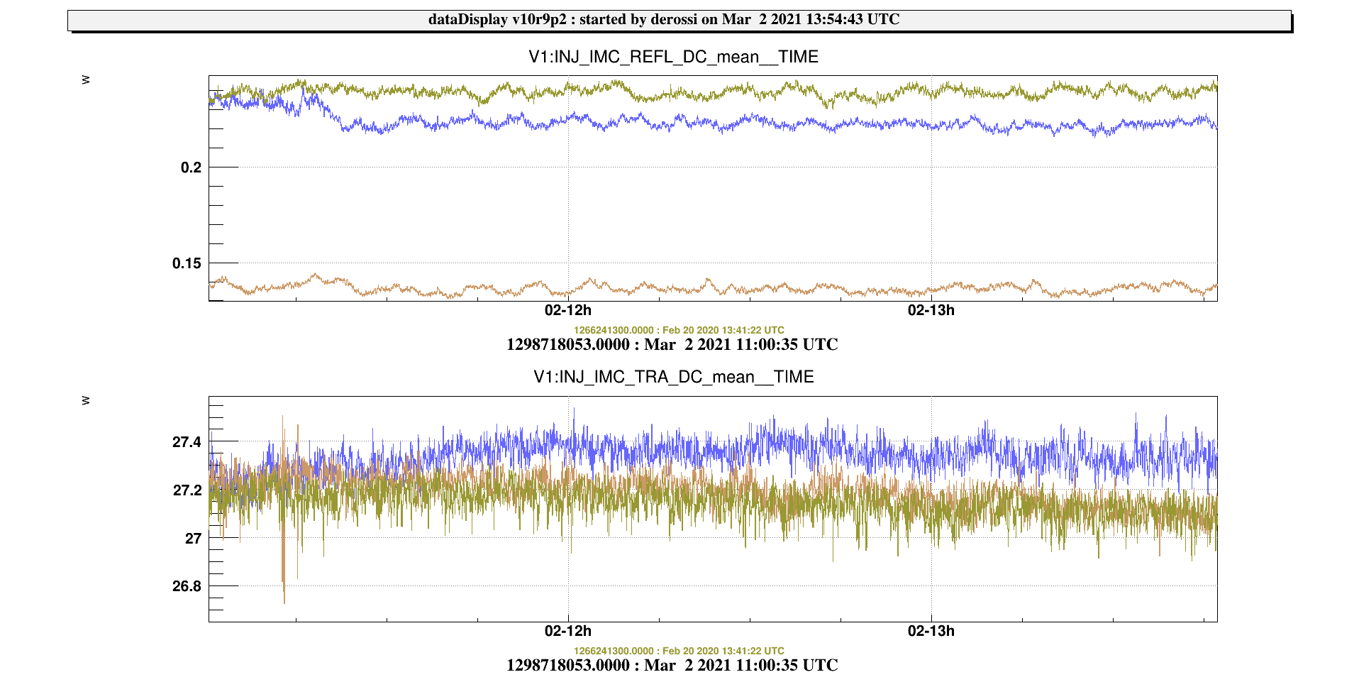
  • we first adjusted the calibration of the INJ IMC TRA signal. It was mistuned by error on the 27th and 29th of January, while working on the EIB for ALS (the attenuation before the photodiode has been moved). We moved this attenuation to maximize the signal and we better clamped it. We took as reference PSTAB PD2 DC which is also monitoring the IMC transmission power: we computed the ratio IMC TRA over PSTAB and we tried to align the beam on the IMC photodiode to recover the previous ratio. We didn't manage to recover it, so we increased the gain of IMC TRA from 7.015 to 7.388 W/V (2nd plot). We measured the power impinging the IMC TRA photodiode after the rectangular density (as shown in the 3rd picture) finding 13.6 mW.
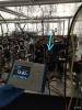
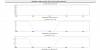
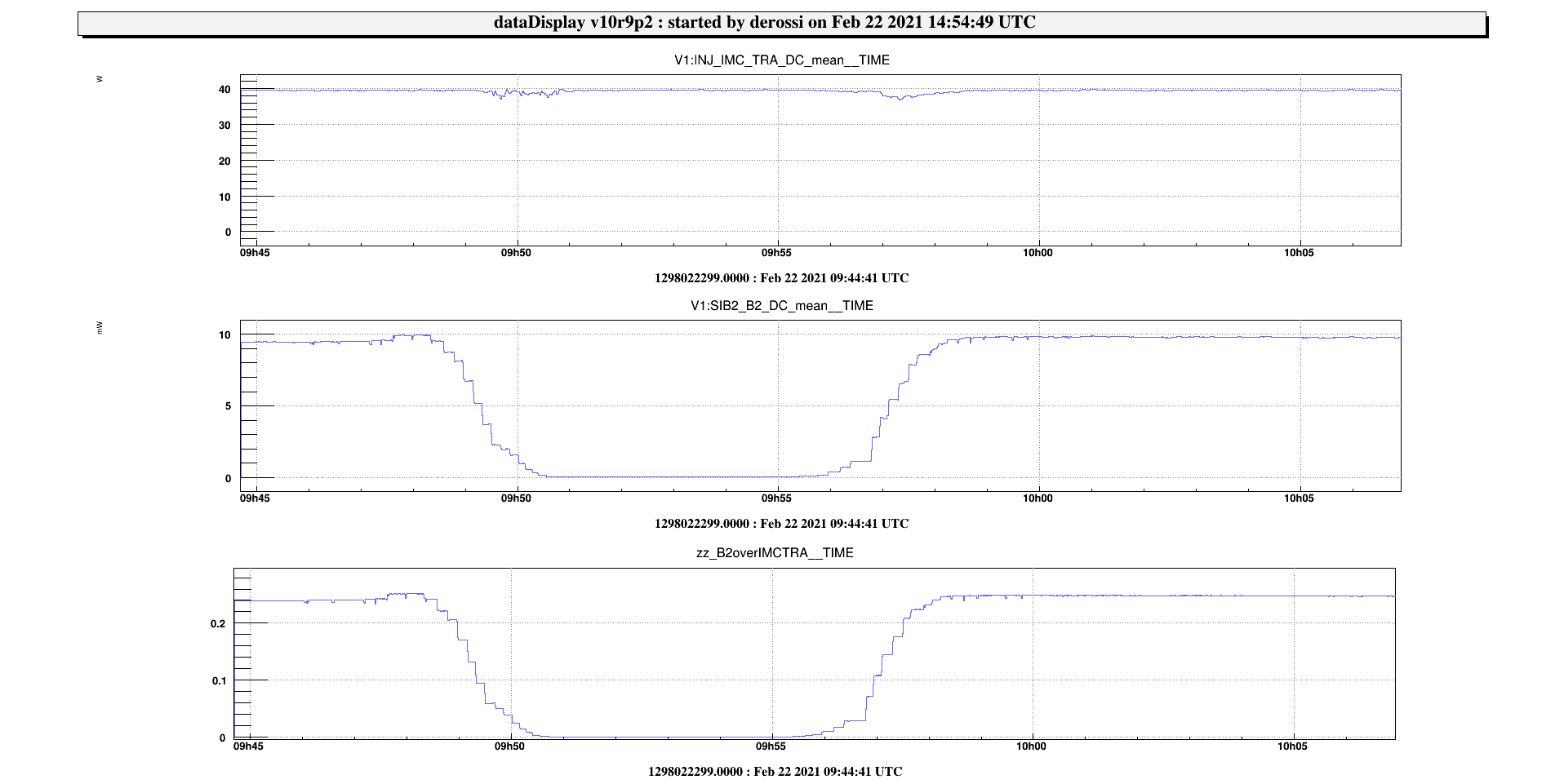
  • we moved the waveplate of the IPC 2 on SIB1 (the actuator is located in the CEB minirack, look at picture 4 ) which changes the amount of power toward the interferometer. We took as references IMC_TRA for the power before the IPC and SIB2 B2 for the power injected to the ITF. In order to have a good signal on SIB2 B2 photodiode the PR was aligned until reaching its maximum (around 10 mW). We realized that we were slightly below the maximum transmission from IPC2. We rotated the waveplate until reaching a minimum (09:50:50 UTC) and we waited some min to collect data with all the light dumped on the BD of SIB1 tower (the water cooled one). We then set it at the max of transmission (look at plot 5). We didn't register any IMC unlock during this operation.
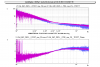
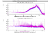
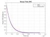
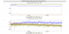
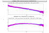
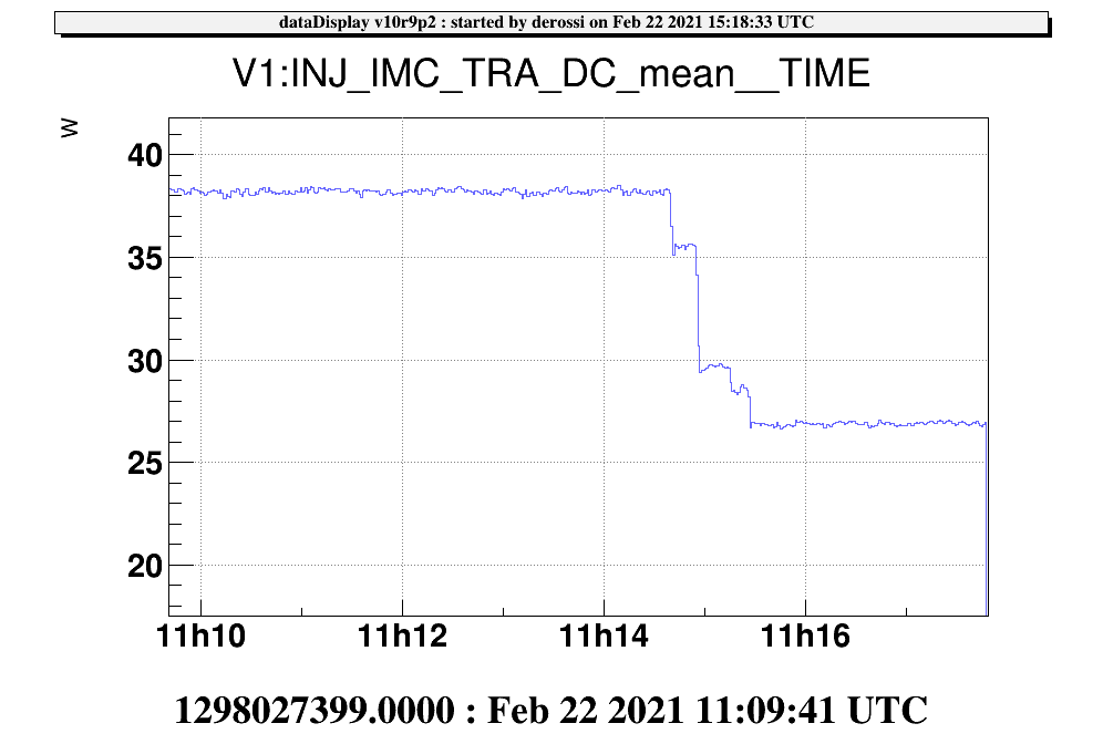
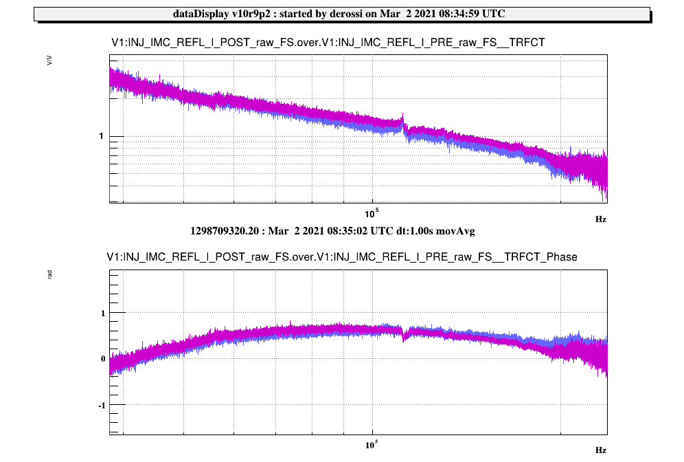
  • we reduced the IMC transmitted power acting on the waveplate of the IPC1 located on the EIB. We directly measured the power going towards SIB1 with the calorimeter: we lowered the power sent to SIB1 from 48.1 W to 34.8 W , which corresponds to IMC TRA = 27 W (plot 6). We made a measurement of the IMC TF and of the spectrum of the IMC error signal and PSTAB error signal (temporarily plugged on the channel named ML D1 TEMP ERR) before and after lowering the power (plots 7 and 8). We had to modify the  attenuation of the IMC error signal from 8 to 6 dB, and we also had to increase the power on the PSTAB phd acting on IPC3 from 1.3 V to 1.6 V (because we noticed some oscillations at 12 kHz, which already were seen when varying the laser power #47534), look at plot 9. We also updated the thresholds in INJ_MAIN.ini for the IMC TRA, RFC TRA locks and also the thresholds in the DSP for the lock of the RFC (from 5 to 4 V).
Images attached to this report
Comments to this report:
melo, spinicelli, derossi, gosselin, chiummo - 20:03 Monday 22 February 2021 (50853) Print this report

Beside the power adjustments, we also collected some data of the decay time of IMC_TRA in order to calculate the round-trip losses before and after the power reduction.

Here the GPS of the two series of 5 times when we unlocked PMC:

Attached one plot that shows the decay time of the signal PSTAB PD2 that we used for measuring the decay time, temporarily plugged to PSL_ML_D1_TEMP_ERR (from 08:55:20 UTC to 13:18 UTC), which has a sampling frequency of 400kHz.

Images attached to this comment
bersanetti - 0:42 Tuesday 23 February 2021 (50857) Print this report

Both cavities were relocked after the intervention; the loop gains were not changed, as we're using normalized signals. The thresholds for the unlock detection and the B7/8_DC_MAX parameters used for the Guided Lock have been updated in the Automation. The cavity transmitted powers are quite more noisy, to be checked if there is some tuning to be done.

Also it was noticed that the demodulation phase of the RFC signal changed by pi/4, but I am not sure whether this was already present before, as the RFC could lock anyway.

Images attached to this comment
chiummo, DeRossi, Melo, Spinicelli - 18:00 Friday 26 February 2021 (50909) Print this report

As it was noticed from the IMC TF plot attached to the original entry, we suffered a substantial decrease of UGF in the transfer function of the IMC. This morning, taking advantage of a break during the ISC activities, we went to the piscina to investigate a bit and found out that it was possible to restore the UGF to reasonable value by decreasing the attenuation of the error signal fed to the rampeauto by 6dB (from 6dB to 0dB).

The UGF was below 50KHz before the intervention, it is now at around 120KHz (see attached plot: purple before intervention, blue after intervention).

This is most likely due to the fact that we did not compensate the power on IMC_REFL when we decreased the power sent to the ITF. This must be done by acting on the IPC8 via the axis 2 channel 1 in the Electronic Injection Room. The target power measured by IMC REFL when the IMC is locked should be of around 0.25V (as it was during O3b), currently it is around 0.14V. We will do it as soon as a window of opportunity opens up.

Images attached to this comment
derossi, gosselin - 15:12 Tuesday 02 March 2021 (50947) Print this report

this morning we increased the power on the IMC reflection photodiode (used for the PDH) to set it back its nominal value In the 1st attached plot the blue correspond to the actual value, set as it was during O3 (green curve), while the light brown one is taken on Feb. the 22nd, after the IMC laser power decrease.

We measured the IMC TF before (2nd plot pink curve) and after (blue curve) this operation and we had to adjust the attenuation on the error signal in order to recover the same UGF of about 130 kHz. The range of lock being between 3 and 16 dB, we set the attenuation at 7 dB.

Images attached to this comment
Search Help
×

Warning

×