From the scan at 22.2 degres during polarization tuning one can try to measure the OMC finesse and sideband filtering.
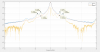
Figure 1 shows the result. The time scale has been rescaled in MHz so that the 6MHz and 8MHz sidebands match their expected frequency (6.27MHz and 8.36MHz). Note that the scan is not perfectly linear, so to match the Airy peak to the carrier TEM00 (normalized to 1 at the peak), the lower and upper RF sideband are slightly offset. But their separation corresponds to the 2f (12.5MHz and 16.7MHz). To match the finesse of the cavity I assumed the OMC FSR is 834MHz (theoretical value), and increased the finesse until the tails of the Airy peak at ~20MHz started to match the data. This yields a finesse of 1100, higher than 900 measured at LAPP using full FSR scans. That higher finesse matches better the expectation from the coating specification that was 0.3% in transmission so a finesse of 1047 (to be checked against the measurement of the sample coated at the same time as the OMC).
The expected transmission of the 6MHz sideband from that Airy peak fit is ~3.7e-3. Slightly better than the 4.4e-3 transmission assumed when deriving the RAM specification VIR-1225B-19. So there shouldn't be issues with the 6MHz filtering.
Note that the P polarization peak lookgs high on this figure with 1% relative power. However the peak B1 PD3 power is 0.58mW, so this corresponds to a peak of 5.8uW, compared to the 58mW transmitted by the OMC. So it is actually only 0.01% of the total power.
Code in /users/mwas/OMC/OMC_scan_20210115