Today we worked on the alignment of SDB1, SDB2, the lock of the OMC and the alignment of SPRB. Details are provided below.
1/ SDB1-SDB2 alignment (with BS+NI+PR aligned):
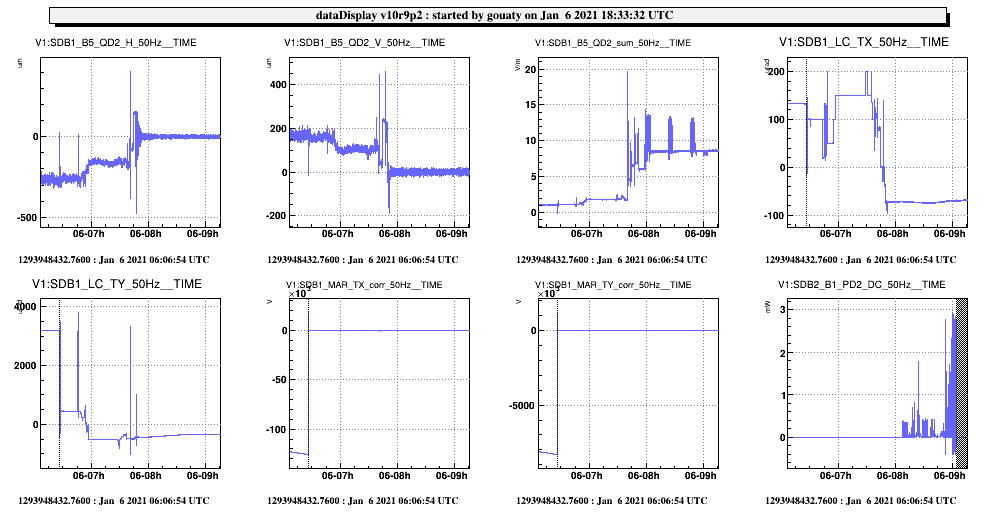
At the beginning of the shift, Michal ajusted the set points of the SDB1 bench in order to have the B5 beam centered on the SDB1 QD2 quadrant. It was then possible to engage the B5 drift control (Fig.1). The new set points of the bench were found to be around TX = -60 urad and TY = -310 urad.
In order to recenter a bit the B5 beam on the camera, we adjusted the TY and TX angular position of SDB2. The SDB2 TX dof was changed from 55 to -220 urad. This was possible by acting on the SDB2 motorized EW counter-weight (+251000 steps allowing to change the correction by +10V). In the end the B5 beam is well centered on the camera horizontally, but it is still 0.95 mm vertically off-centered (but we cannot do much better due to the limited range of the counter weight).
We acted on the picomotors of SDB1_OMC_Ref1 in order to center the B1s beam on the camera.
We then proceeded with the alignment of the B1p photodiodes and camera. The B1pP PD was centered by acting on SDB1_M4 picomotors (several thousands steps in TY) and on SDB2_B1p_M4 picomotors (H:-1000 stps, V:-8500 stps). The B1p camera was centered with B1p_PBS (H:-1300 stps, V:-1100 stps). B1p_PD2 was centered with B1p_M5 picomotors (H:+7000 steps abd V:+3000 steps). B1p_PD1 was centered with B1p_M6 picomotors (H:+5000 steps abd V:-5000 steps). The centering of the B5_PD1 and B5_PD2 photodiodes was also checked.
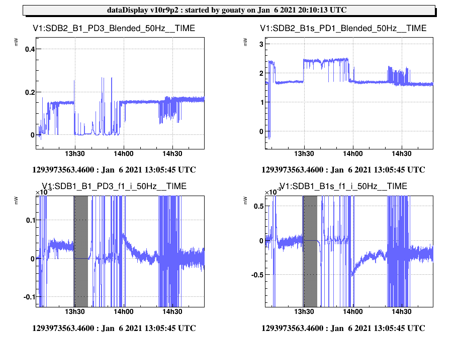
In parallel, Michal aligned the OMC cavity with the ITF beam. He then managed to lock the OMC using the photodiode in reflection (B1s_PD1), which allowed to center the B1 beam on the new B1_PD3 photodiode. Then Michal worked on the lock of the OMC using the B1_PD3 photodiode, which was achieved around 14h00 utc (Fig.2).
During this activity we noticed that the quadrants of the SDB2 bench are not responding. After some preliminary check, we think that this is related to a malfuntion of the ethernet bridge used to drive the quadrants. This requires further investigations.
We also noticed that the shutter of the B1_PD2 photodiodes was not triggered by a DC power of almost 5 mW. Although the safety threshold cannot be lowered (without preventing rearm of the Vbias), this behaviour may put the photodiode at risk of laser damage.
The next steps concerning the OMC will be to adjust the polarization matching between the ITF beam and the OMC, to recenter the B1 beam on the B1_PD1 and B1_PD2 photodiodes (although the B1_PD2 is already roughly aligned as we observed several mW on this photodiode, but no light was seen on B1_PD1), and to go on the work on the OMC lock.
2/ SPRB alignment (with BS+NI aligned):
We adjusted the setpoints of the SPRB bench in order to have the B4 beam centered on the camera. Then we centered the beam on the B4_PD1 and B4_PD2 photodiodes. To this purpose we used the picomotors of Mmot3 (H:-22500 stps, V:+11500 stps) and Mmot4 (H:-9500 stps, V:+15000 stps).
The also centered the B4_QD1 and QD2 quadrants, acting on Mmot1 and Mmot2 (order of 1000 steps).
After changing the sign of the gains of each galvo loop, we could engage the galvo automatic centering (Fig.3).
3/ Changes in configurations
We updated the configuration of the SDB2 DAQ box and the SDB2 photodiode process, to perform the following changes:
- The channels referring to the B1s1 and B1s1P photodiodes were removed ;
- The channels referring to the B1s2 photodiode were renamed into B1s.
- New channels referring to the B1_PD3 photodiode were added.
We also swapped the channels B4_PD1 and B4_PD2 in the configuration of the SPRB Dbox, in order to reflect the naming convention used in Optocad.
