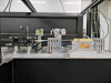
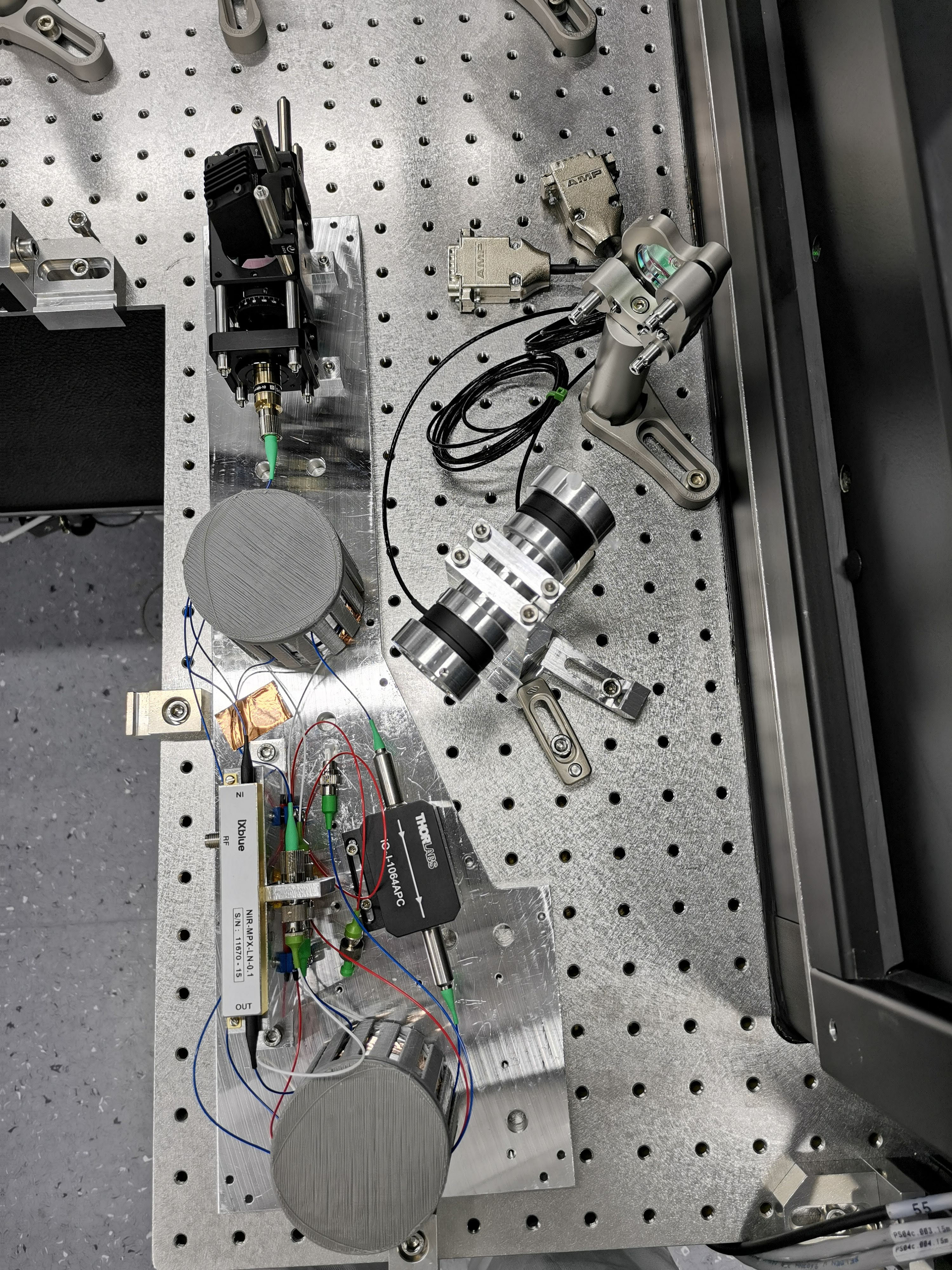
The box containing the optical isolator, the beam splitter and the EOM (all in fiber) has been installed on the ESQB1 bench. See sketch “SC_3D.pdf”, the pictures “SCBox1.png” , "SCBox2.png" and the optical scheme “laserSC.pdf”.
In order to place the box in the bench we had to move a clamps clamps of the LO PZT mirror fo the homodyne CC.
We have encountered problems in coupling the laser output fiber with the Faraday isolator input (see below).
So first we characterized the system by injecting the light into the fiber port "A" (the port labels are written with green background in "laserSC.pdf") using the in fiber signal coming from the PLL (1 mW of the SQZ main laser pick off) and not the SC laser fiber output (entry#50159).
These are the powers measured (refer to figure "laserSC.pdf" for the port names)
| Port name | Position | Power (mW) |
| A | Input Port | 1.05 |
| C | Faraday Output | 0.76 |
| E | 99% beam splitter out | 0.655 |
| F | AOM output | 0.330 |
| G | Collimator Output | 0.32 |
| I | HWP maximum output | 0.306 |
The power losses along the optical line are significant and require further investigation.
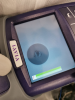
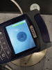
However the major problem we encountered are in connecting the fibers “A” “B”. The Schafter APC connector plugs with difficulty into the Thorlabs fiber mating. After forcing a bit by injecting 480 mW into "A" we got only 30 mW at "C" much less without forcing. At some point we found a dramatic worsening of this behavior. We then inspected the output of the Schafter fiber ("A") and the input of the thorlabs fiber "B" , finding some "halos" (figures "SC_out.png" "FI_in.png" ) that we could not clean in any way. We did not understand if the fibers are damaged or dirty. We are considering polishing these two fiber ends.
At the end of shift day we decided to leave the system in such a configuration that people can continue to work on the alignment of the SC line (see entry# 50178): we connect the input of the EOM ("E") directly to the collimator output of the PLL. In this way we left 3mW as output of the SC box ("I"). This should allows to work at the mode matching of the SC beam to the OPA and to install all the SC optics on the bench.
