Since the beginning the green beam was reaching the WI mirror (at about ~5cm from the center (very rough estimate))
The beam luminosity on the WI was varying. To verify that this was not due to cavity flashes we misalign the WE mirror by 100 microrad in Ty. The beam luminosity variation remained unchanged. The reason of this luminosity variation is not very clear.
Using the Galvo 2 we tried to center the beam on the WI mirror. We did not succeed since the beam was clipping on the SWEB telescope mirrors before reaching the center of the WI mirror.
We then tried to center the beam on the WE. Moving Galvo 2 we were able to send the beam on the right side on the baffle placed at the back of the WE mirror. But we were not able to send it on the left side since, once again, the beam was clipping on the SWEB telescope mirrors before reaching the left side on the WE baffle.
During the afternoon with the remote help from Julia, Paolo, Marco and Antonino we were finally able to have the west arm cavity locked using the B4 photodiode (i.e. in reflection). In this configuration we were able to check the relative position on the IR beam and of the green beam on the SWEB mirrors. The two beams were fairly well overlapped on the last dichroic mirror, but they were not well overlapped on the M4 mirror. Moreover the green beam was quite misaligned on M3, M2, M1 and L1.
From there we started moving the last dichroic mirror (i.e. the one closer SWEB telescope) in order to center the green beam on these optics. By doing this we were able to get the green beam closer to the center of the WI mirror. Unfortunately in this situation the green beam reflected by the WE mirror was passing through the Galvo2 but not through Galvo1. We then start moving again the last dichroic to get the beam reflected by NE through Galvo1. We managed to do that (at the expense of moving the beam farther from the center of the WI input mirror).
We install a mirror to send the reflected beam on the camera.
The reflected beam has the usual ugly shape.
21h30 time to go to dinner.
Here it will be described the procedure applied to reach a lockable arm starting from 'no flash' state.
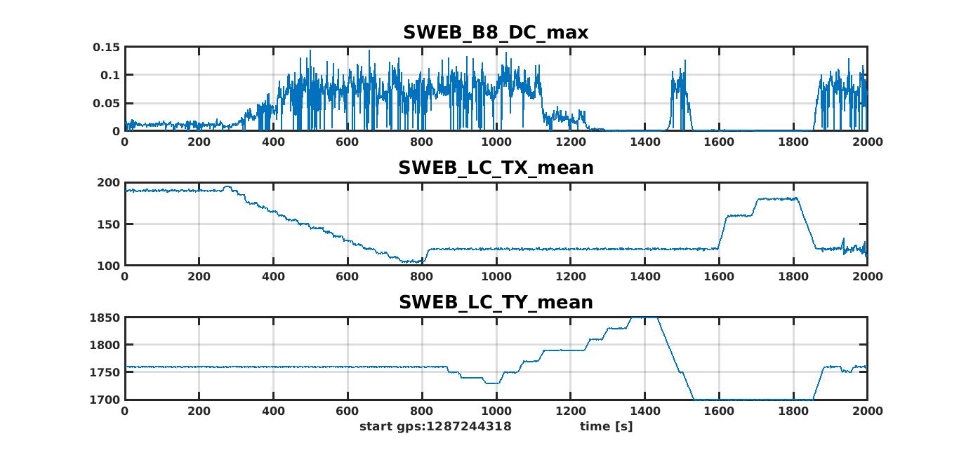
First of all, the mirrors (BS, WI, WE) have been placed at the same values recorded by the optical levers at the time of the latest 'flashing' state. One can find the good gps plotting the trend of the channel SWEB_B8_DC_max.
In the table: the values at the good gps; the current values at the beginning of the alignment; the additional offset to apply to the LC set points. N.B: inserting the good recorded values as new set points in the DSP cards does't work, because those numbers are not the only offsets. There are also the offsets added by the automatic alignment system, recorded in internal variables. One has to add the difference between the current and the requested values of the signals in the data, and check that the signals at the end are correct.
| latest good values | current values | offset to apply | |
|---|---|---|---|
| BS_TX | 80.7 | 58.7 | 22 |
| BS_TY | -30.8 | -38.8 | 8 |
| WI_TX | 30.2 | 0 | 30.2 |
| WI_TY | -26.4 | -45 | 18.6 |
| WE_TX | -24.3 | -26.4 | 2.1 |
| WE_TY | 44.7 | 32.5 | 12.2 |
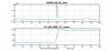
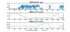
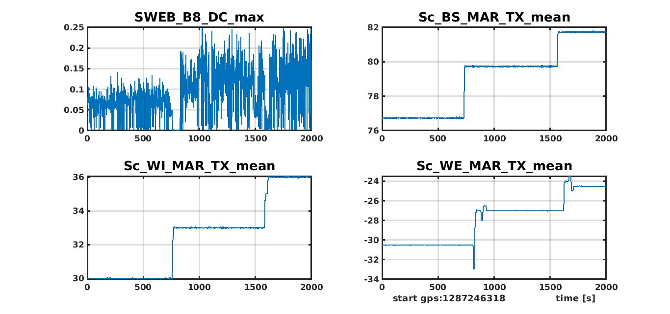
During the restoring of the old position, a first flash was seen (fig 1). At this point, the normal procedure of random search of higher flashes started. In order to be more efficient, it can be useful to look at the image of flashes on the camera. Also looking at the reflection of the input mirror on B4 camera could be useful: it should be not far from the center. But also a 'blind' search, as I did yesterday, usually can easily lead to improve the flashes at least up to 0.1 on SWEB_B8_DC. Since I was not able to do that, I asked to do a scan of SWEB position. The result was the desired one: flashes of more than 0.1 were obtained (fig 2).
At this point, the information from WE camera was talking about a vertical misalignment. The flashes were still maybe too low to be locked, so a further attempt to improve the cavity alignment was done. Unfortunately, from this condition the adjustment of a single mirror never works: any single change leads to a lowering of the flashes. Any possible improvement needs always a combination of motions. The possibilities are two:
1) the beam direction is correct, but the optical axis is shifted;
2) the beam is pointing out of the END mirror center.
In the first case, a combination of IN and END mirror adjustment is needed (even up to several urad for both). In the second case, all the three mirrors has to be moved (up to several urad too).
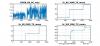
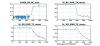
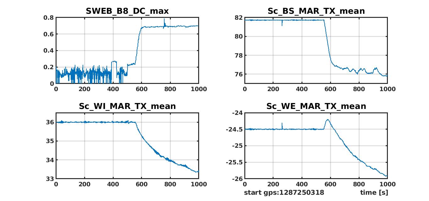
Yesterday I tried a different vertical orientation of the beam (BS_TX), the amplitude of the flashes was doubled, but a further step did not give any improvement (fig 3). The flashes were high enough to try a lock, and in fact the lock was acquired and the automatic alignment made the final step: BS_TX was put back to the position before the step of fig 3 (which was evidently a wrong choice), and a shift of the optical axis was performed (fig 4).