The power stabilization system might be the origin of the 250Hz line visible in h(t), and also a non negligible contributor to the 50Hz (and to a lesser degree 150Hz). With the photodiode signal being spoiled by 50Hz harmonics and the being impressed onto the laser amplitude.
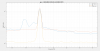
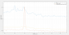
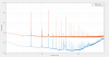
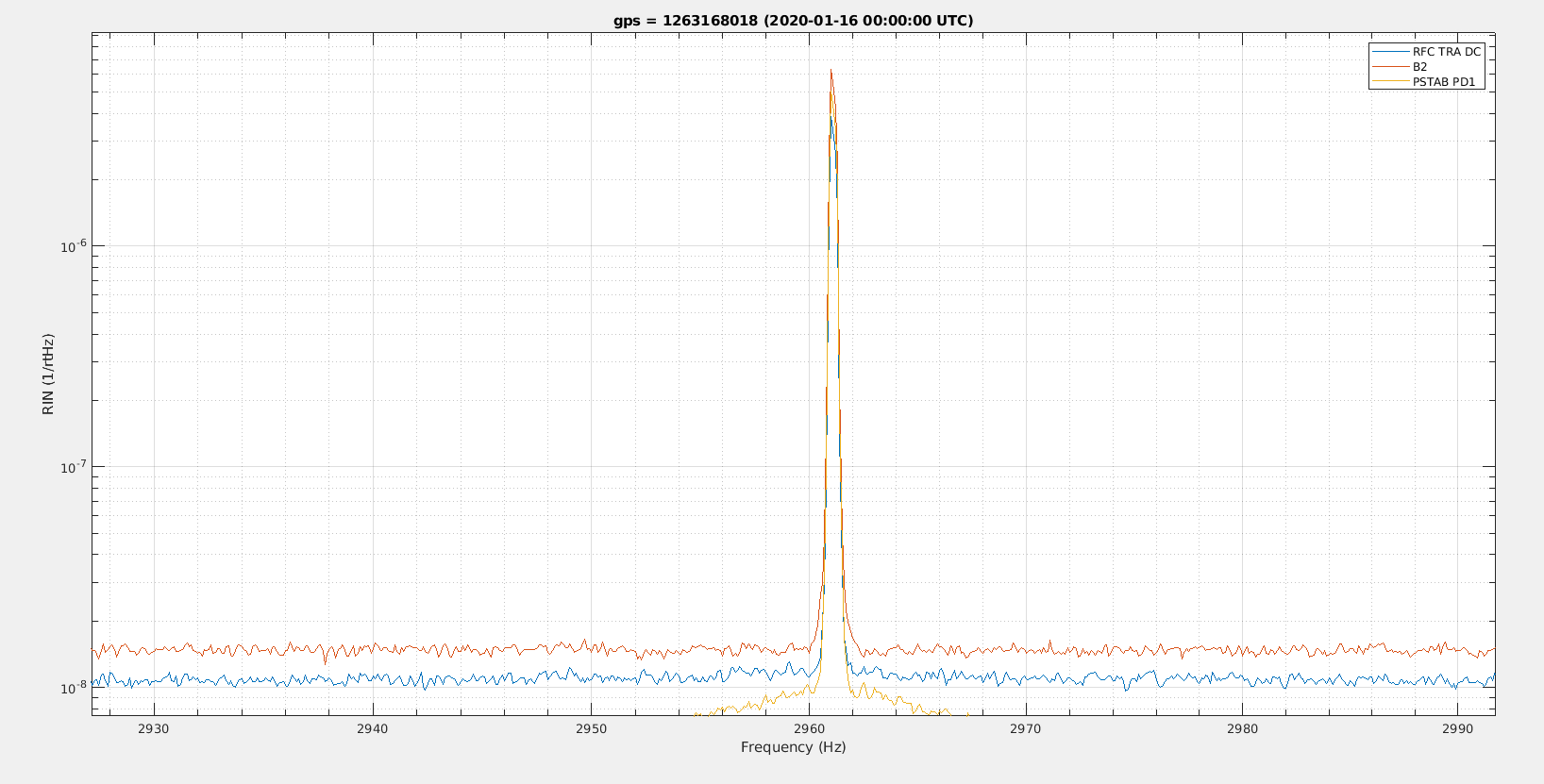
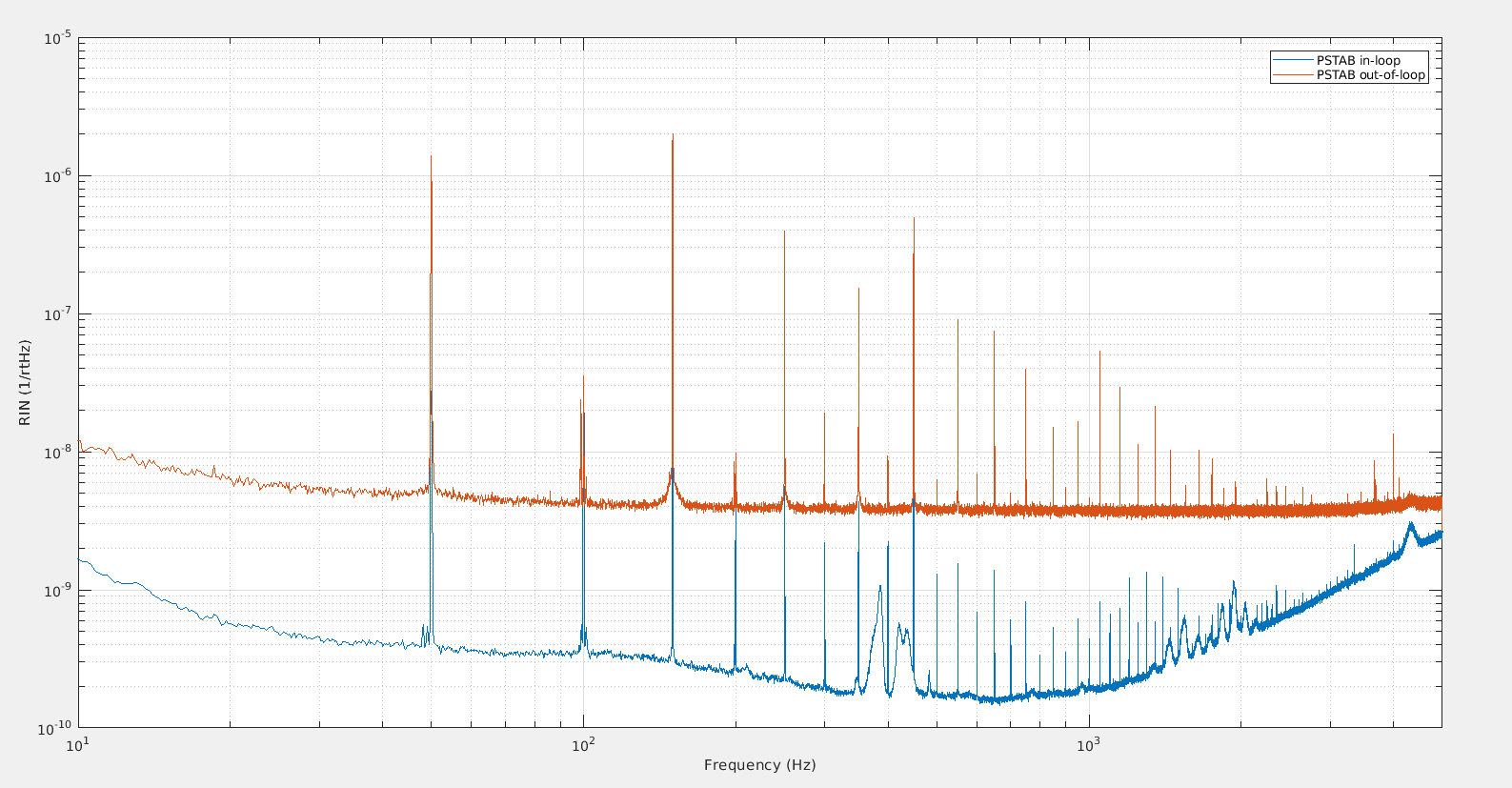
Figure 1 shows the relative intensity noise as measured by the PSTAB out-of-loop photodiode, the B2 photodiode and the RFC TRA photodiode. The spectra are very different, but the 50Hz and 250Hz lines have very similar height in the three signals.
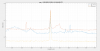
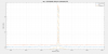
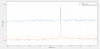
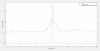
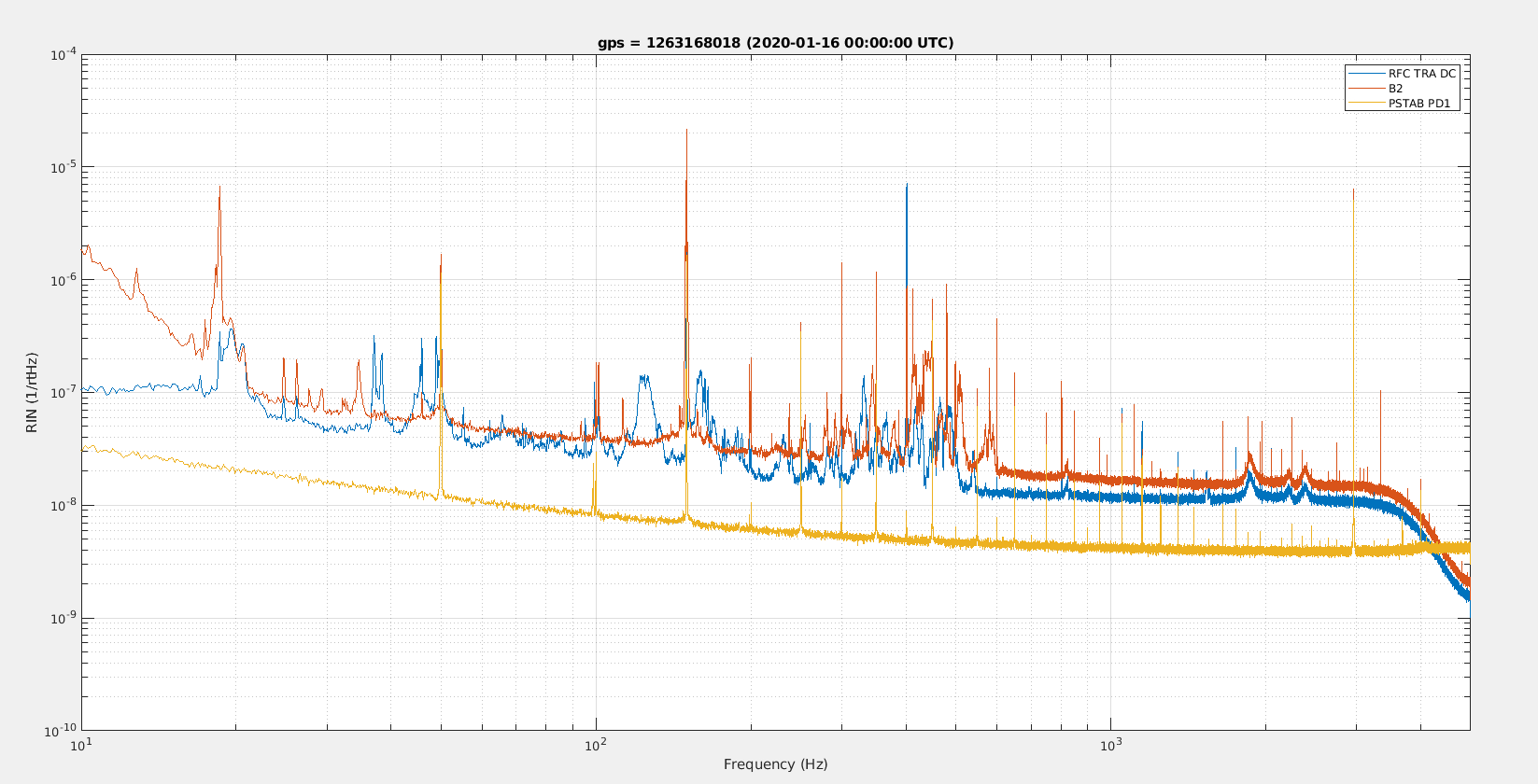
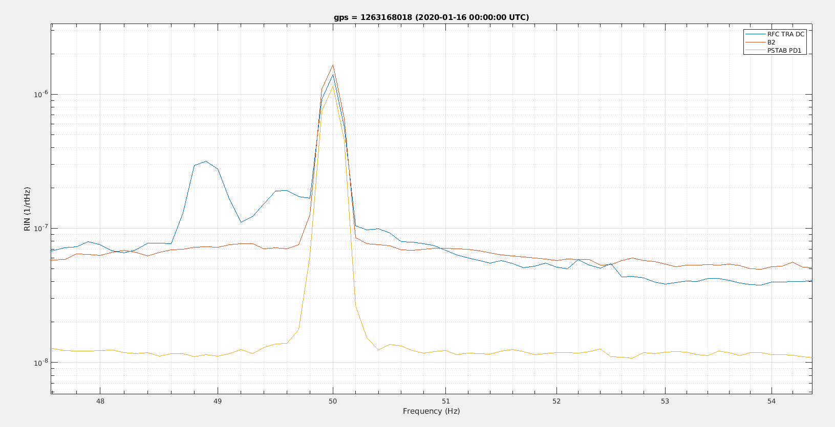
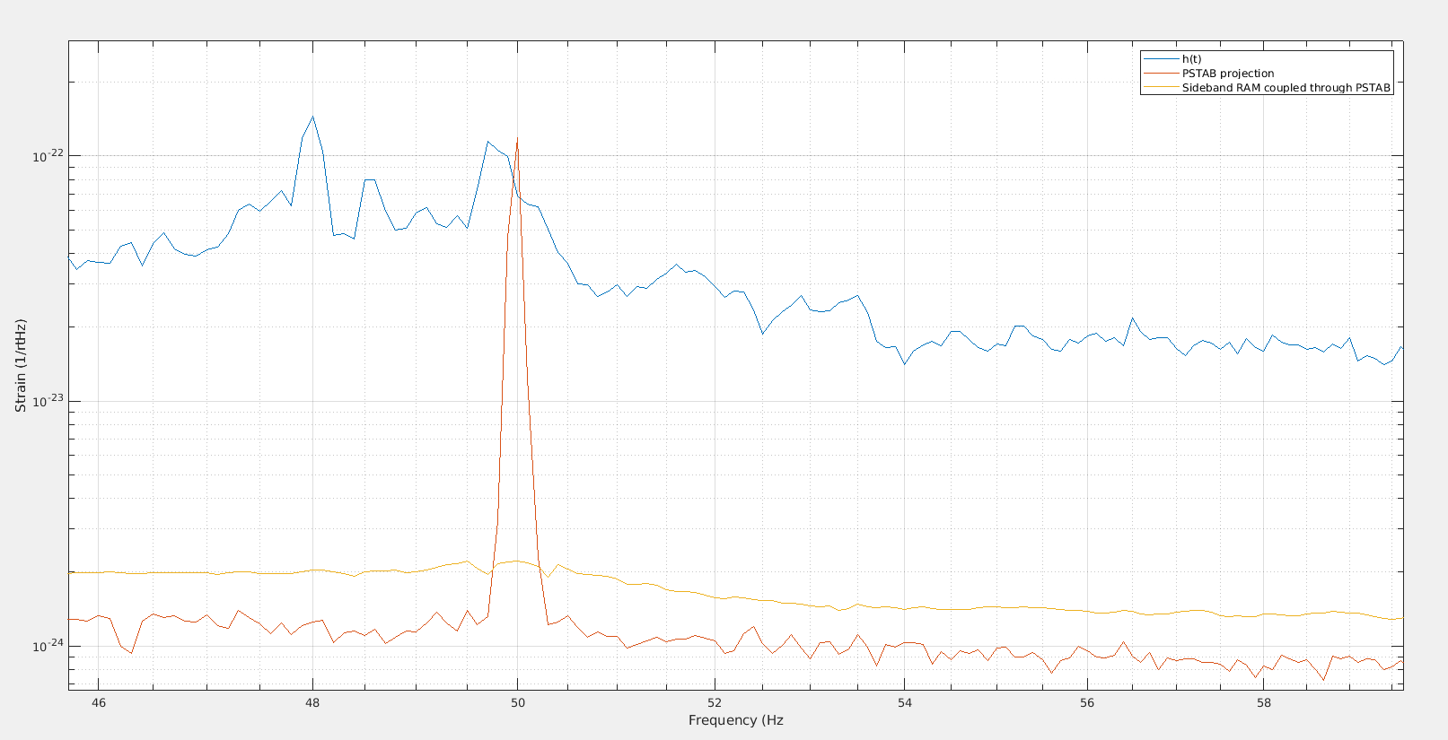
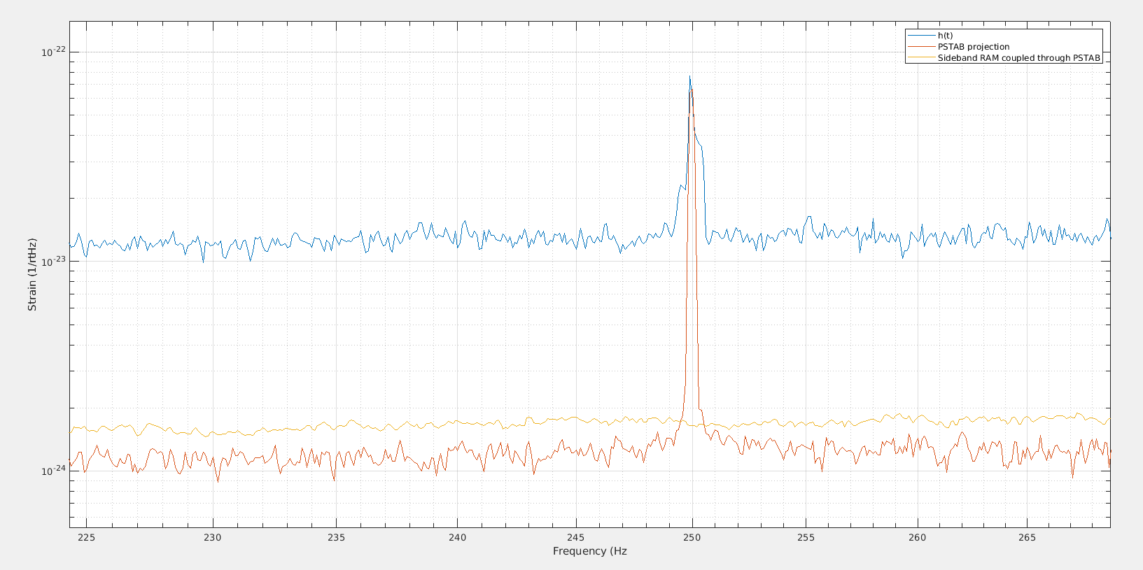
Figure 2 shows a zoom around 50Hz, and figure 3 a zoom around 250Hz.
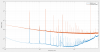
Figure 4 at that time (Jan 16) there was also an intentional line injected into the PSTAB loop at 2961Hz. The amplitude of that line seen in the 3 signal is not exactly the same, but it is within +/-20%, which confirms that the 3 signals RIN is indeed comparable.
/users/mwas/detchar/PSTABcoupling50Hz_20200205/RIN.m
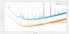
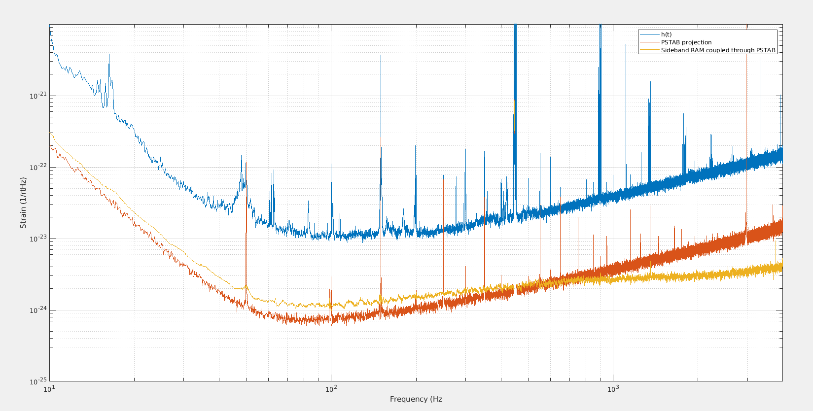
When doing a projection of the PSTAB noise to h(t) using a measured TF from July 2019 the projected 50Hz and 250Hz are at a similar level as what is actually seen in h(t).
Figure 5 shows the broadband projection.
Figure 6 is a zoom at 50Hz, where the projected noise is slightly higher than what is measured, this could be due to 50Hz feed-forward technique removing some of the 50Hz coupled by the PSTAB by acting on the arm mirrors.
Figure 7 is a zoom at 250Hz, where the projected line matches well with the measured noise in h(t).
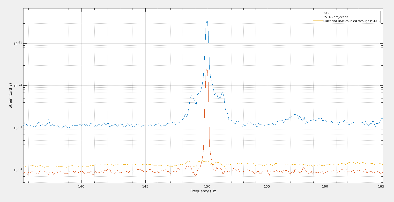
Figure 8 is a zoom at 150Hz, where the projected line is a factor 10 smaller than the measured noise in h(t), so for the 150Hz something else than the PSTAB is the main culprit for the coupling.
I wonder if there is any improvement that could be implemented after O3 to reduce the 50Hz odd-harmonics in the PSTAB photodiodes, and if these harmonics are due to the PD itself or to the signal propagation along long cables inside the IB tower. These harmonics are a factor 100 above the PD broad band sensing noise for FFTs of 10s duration (see figure 1).
