7:30 UTC (30min) reference time in Science mode
around 8:05 UTC unlocked due to mistake (reducing DARM offset without a ramp)
relocked at second attempt
8:42 UTC (5min) reference time after relock (same range as before unlock)
reduced dark fringe offset
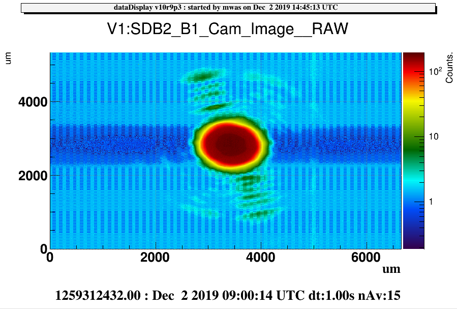
9:00 UTC (5min) dark fringe offset at 1mW per B1 PD (instead of 2mW) and Hrec has adjusted the optical gain. DARM_SET=0.00032 and DARM_GAIN = 12.0
improved BS TY and TX alignment to reduce CD (contrast defect on B1p)
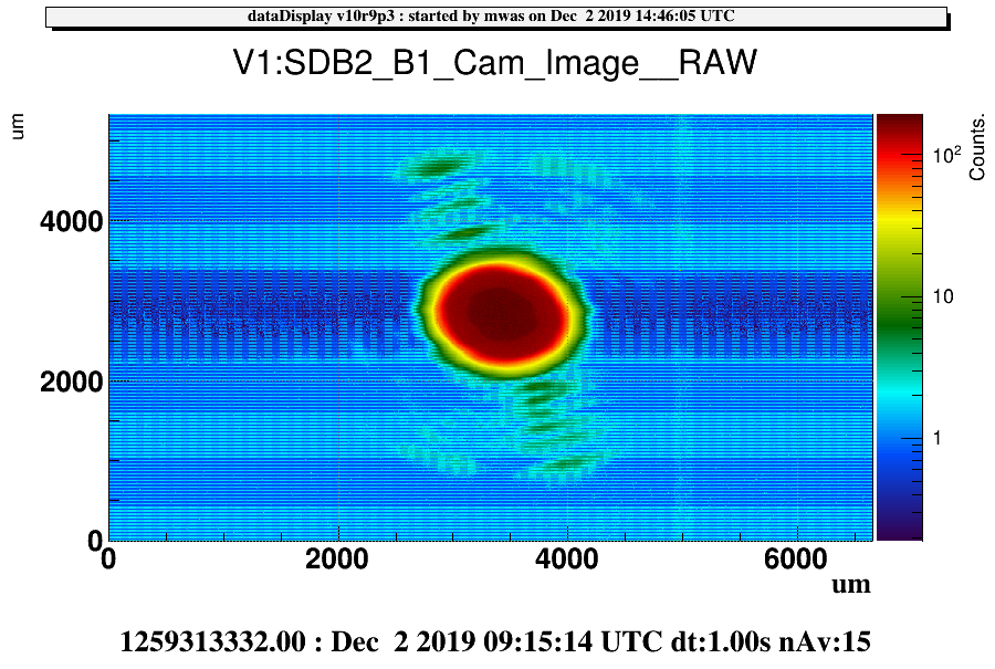
9:15 UTC (5min) range is worse with this alignment, noise is higher from 50Hz up to a few kHz, ITF optical gain goes down by 1%
put back initial alignment
9:25 UTC (10min) good data with dark fringe offset at 1mW per B1 PD
going back to nominal dark fringe offset
9:45 UTC (10min) good data with dark fringe offset at 2mW per B1 PD
Relocking with negative DARM offset, change the offset sign in ITF_LOCK.ini, the sign of DARM demodulated OMC signals OMC_LOCK.py and sign of B1 in Hrec_hoft (keeping HrecClean_hoft with nominal sign for comparison)
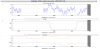
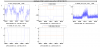
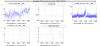
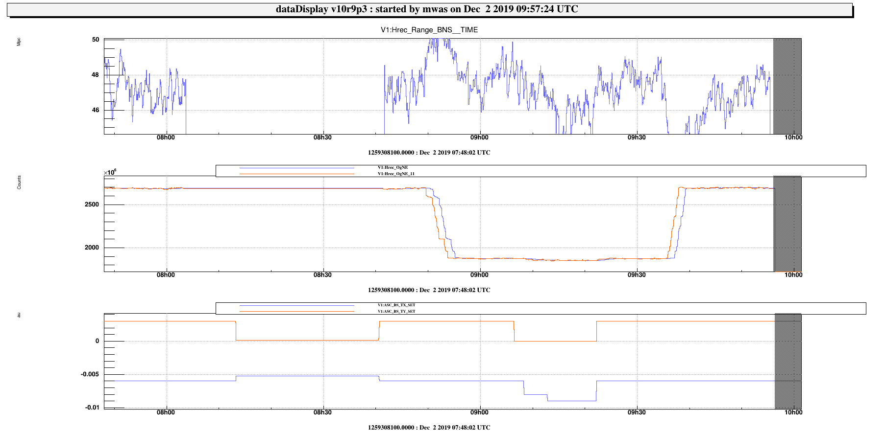
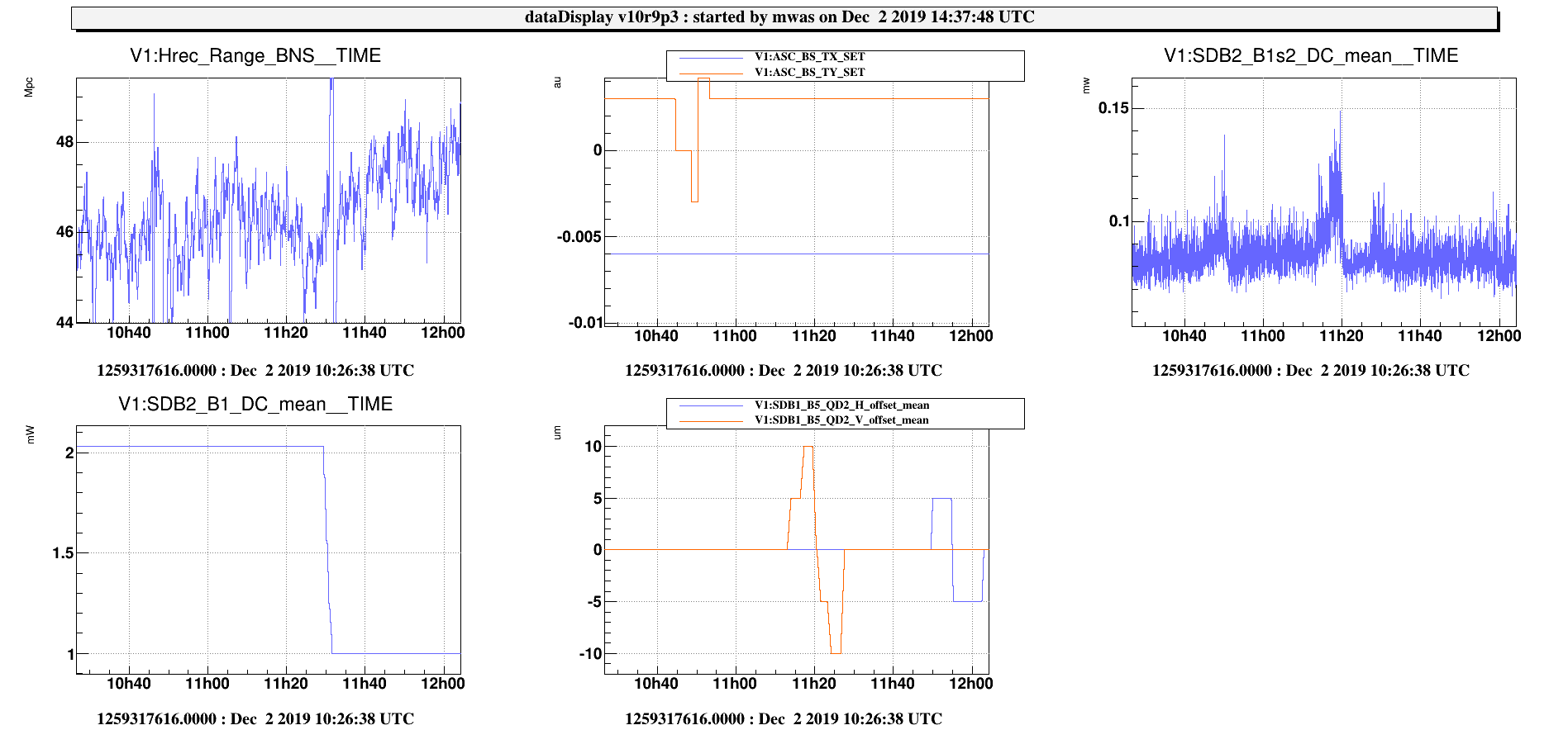
Figure 1 shows the range, dark fringe offset and BS alignment signal trends, the reduced dark fringe offset may have a small impact of improving the range by ~1Mpc, but it is hard to say the range itself fluctuates by +/-2Mpc.
10:18 UTC relocked with a negative dark fringe offset, sensitivity is bad due to a bad alignment working point
Adjusted the DIFFp and BS working point, h(t) and CD don't agree on what is the best alignment point (it was already the case for the positive dark fringe offset)
11:00 UTC (12min) data with optimized alignment working point
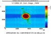
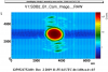
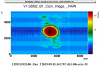
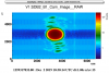
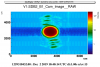
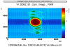
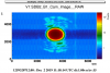
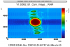
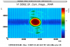
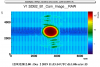
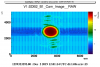
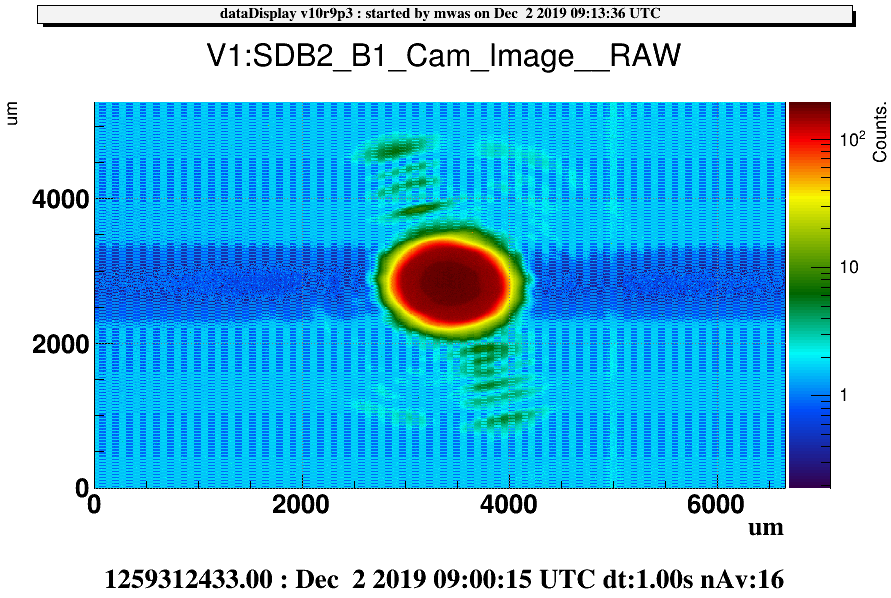
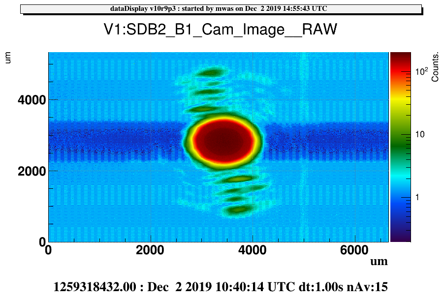
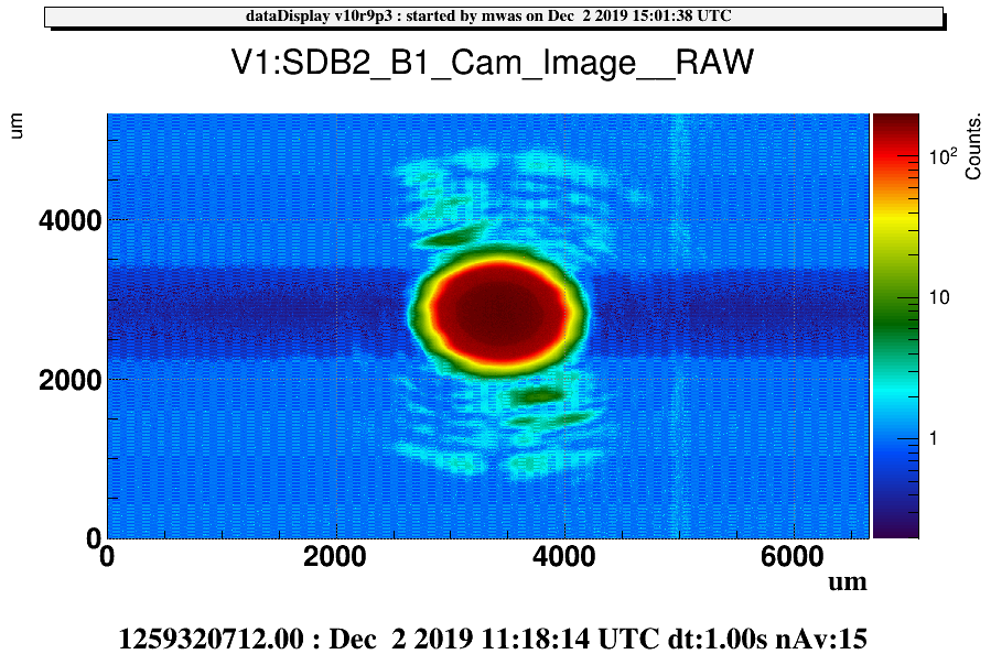
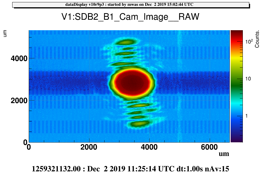
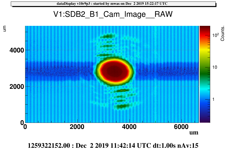
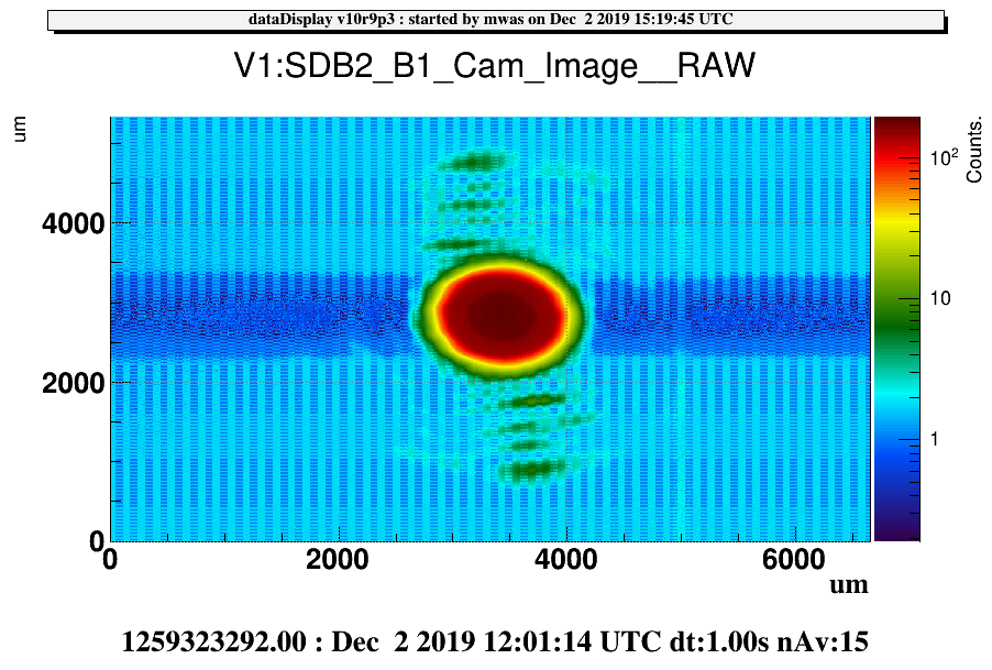
Figure 2 shows the HOM on B1 with 1mW of positive dark fringe offset and Figure 2 with 1mW of negative dark fringe offset. The HOM content is different. In the latter we have seen that the SDB1 angular offset has not much impact on the range, unlike what we have seen with the positive offset a month ago. To be checked on the camera images if there is no impact of the SDB1 angular offset on B1 HOM shape with a negative offset.
between 11:12UTC and 11:27 UTC tried SDB1 vertical alignment offsets, not much impact on the range and with zero offset close to optimal ITF gain
lowered DARM offset to -0.00032 with DARM GAIN at 12.0
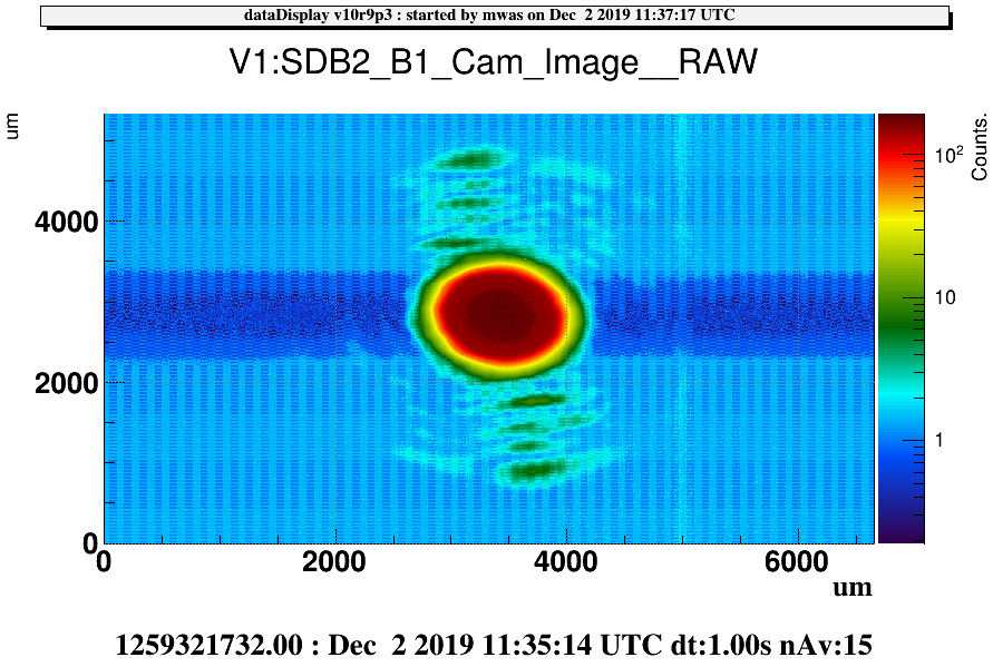
11:35 UTC (14min) good data with lowered dark fringe offset, 1mW per B1 photodiode
adjust SDB1 horizontal alignment offset, no impact on the range
Going back to the nominal configuration (DARM offset positive, and 2mW per B1 photodiode).


