Reports 1-1 of 1 Clear search Modify search
AdV-COM (AdV commissioning (1st part) )
casanueva, brooks, bonnand, gouaty - 15:19 Thursday 21 November 2019 (47751) Print this report
SPRB scans

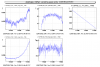
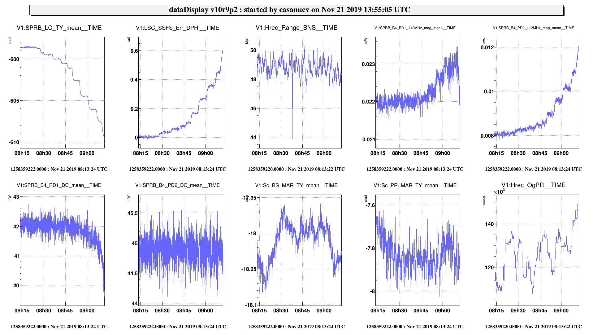
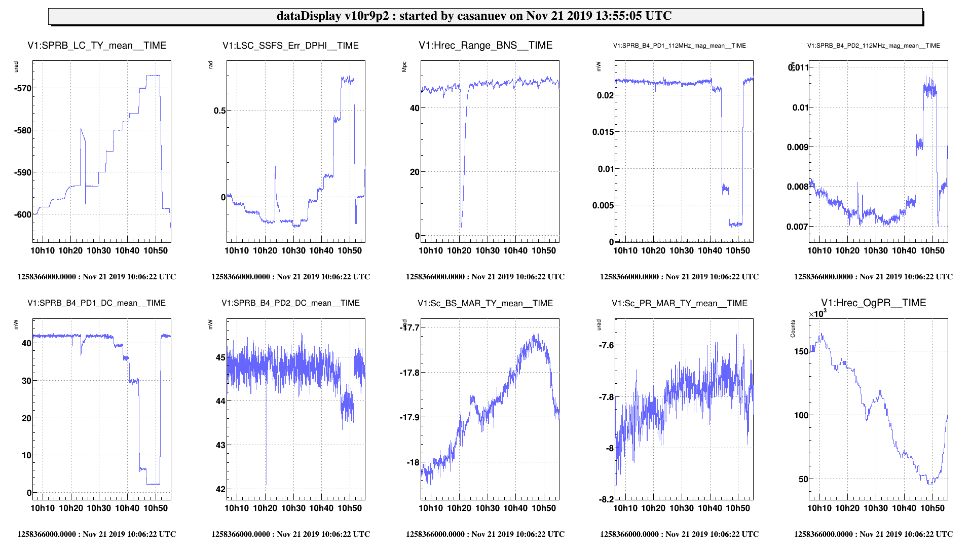
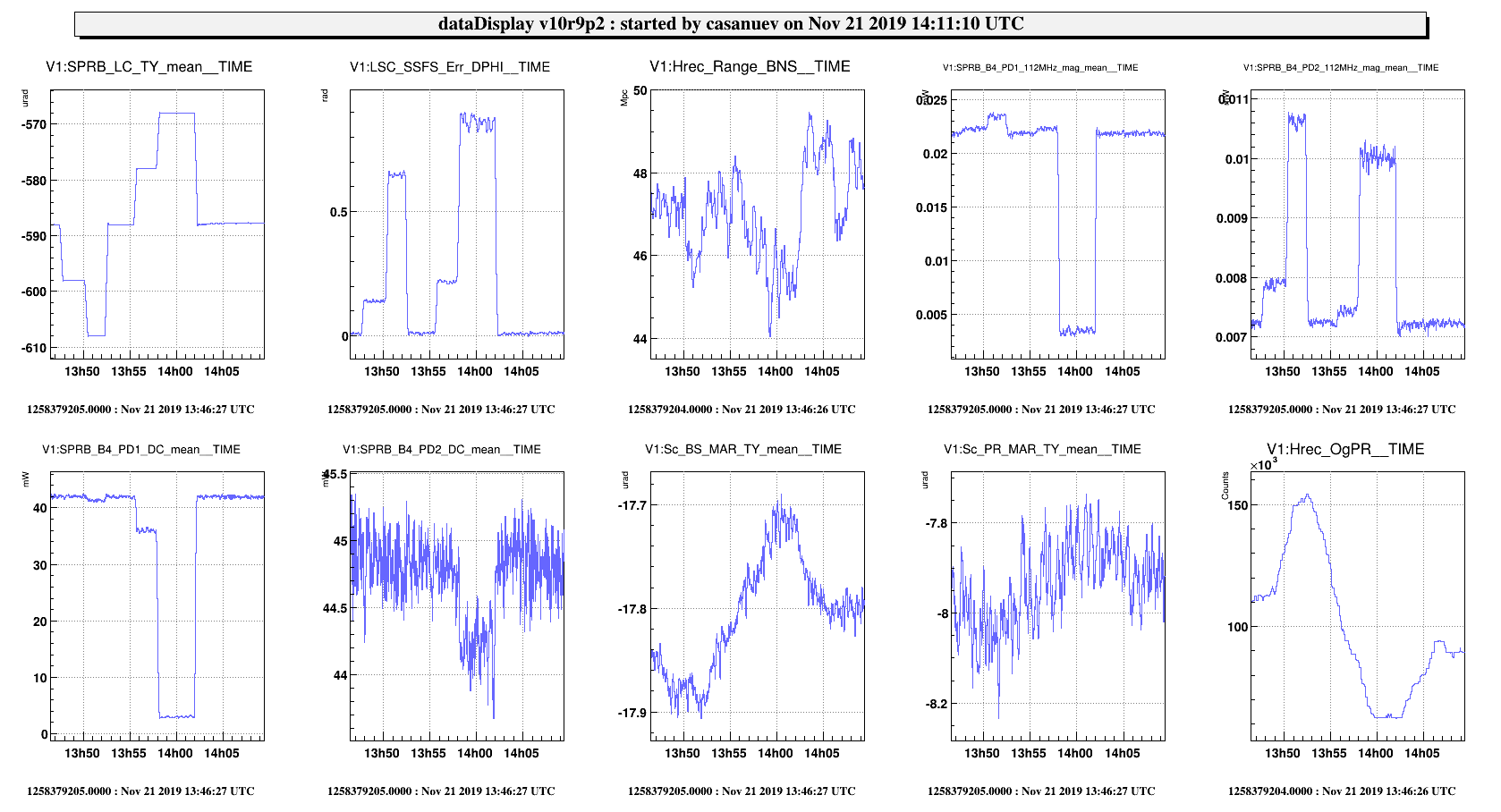
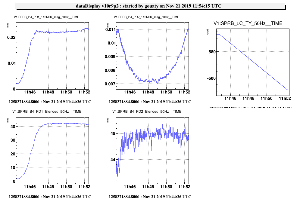
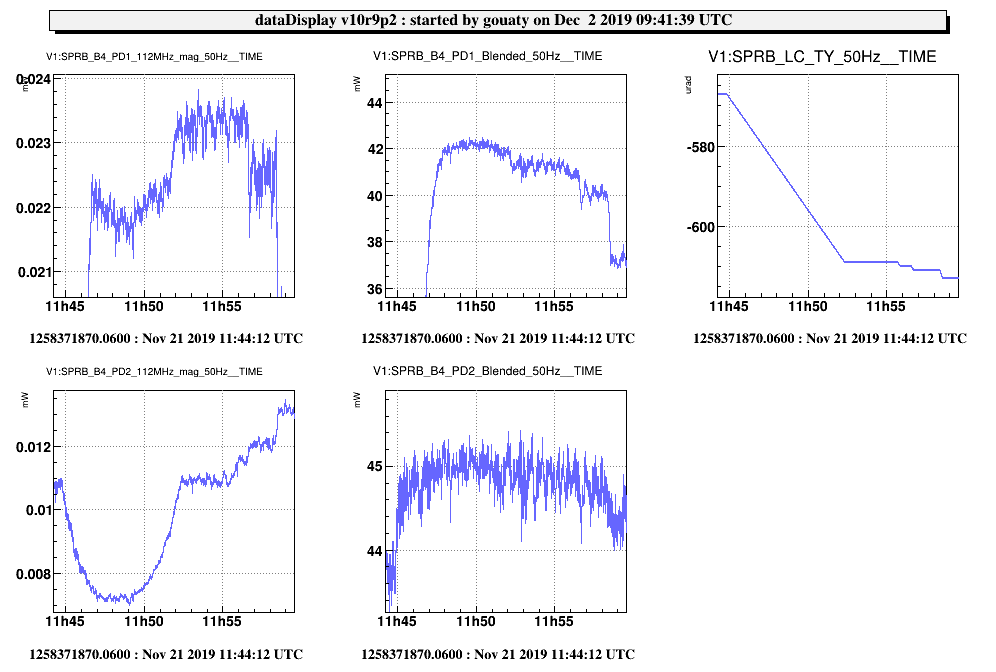
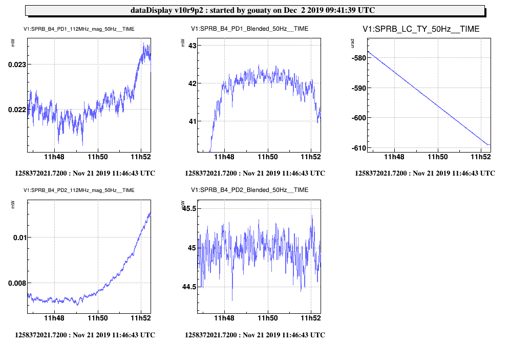
This morning the Romains have made several scans of the SPRB bench. We have observed several interesting things, that need a more careful analysis, but in this entry we plot the relevant scans for reference

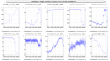
We have observed the usual opposite behaviour between carrier / 56MHz on PD2.

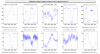
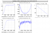
We have osberved that the DPHI of the SSFS (which uses B4 PD2) changes as the bench moves.

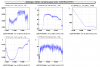
We have also noticed that the BS and PR mirrors move angularly during this test, as well as OgPR.

*During the shift we had some problems with the lock acquisition, in particular during OMC1 lock the ITF was too misalign. So I restored a different offset for the DIFFp_TY during the lock of the OMC1, to keep it aligned.

Images attached to this report
Comments to this report:
bonnand, gouaty - 18:11 Thursday 21 November 2019 (47755) Print this report

We also scanned the TY position of SPRB in low noise 1 in order to better check the "edges" of the photodiodes plateau (see Fig.1). Although not visible in Fig.1, we could see the power on PD2 starting to decrease after doing 2 or 3 more microrad in the negative direction. Thus Fig.1 shows almost the whole plateau of PD2.

After this scan, we set the TY position of the bench at -588 urad (position reached at 11h48m30 on the plot) as it is near the center of the plateau both on the DC and 112 MHz channels of PD2. In order to set this new position with the bench drift control engaged, an offset (-7V) was added to the correction of the galvanometer mirror placed in front of the QD2 quadrant.

Images attached to this comment
tacca - 11:51 Friday 22 November 2019 (47761) Print this report
The B4 phase camera was slightly misaligned changing the angular working point of SPRB. This morning it has been realigned.
gouaty - 13:10 Monday 02 December 2019 (47835) Print this report

The scan of SPRB in TY performed on Nov 21 allows to check what would be the best setpoint to have the PD1 photodiode well centered. Looking at the blended signal of PD1 (Fig.1 and Fig.2) on can see that the middle of the plateau is around TY=-595 urad. The bench was adjusted to -588 urad in order to optimize the centering of  PD2. Thus the bench setpoint should be adjusted by -7 urad in order to have the best centering on PD1 (with the current position one can see from Fig.2 that the power on PD1 is ok, but there is not a lot of margin with respect to the edge of the plateau).

Images attached to this comment
Search Help
×

Warning

Error

The present report has been modified outside this window. Please check for its integrity in the main page.

Refreshing this page will move this report into drafts.

×