Reports 1-1 of 1 Clear search Modify search
AdV-INJ (Reference cavity (RFC))
derossi, gosselin, chiummo, nocera - 18:26 Friday 15 November 2019 (47680) Print this report
RFC TRA photodiode replacement

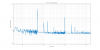
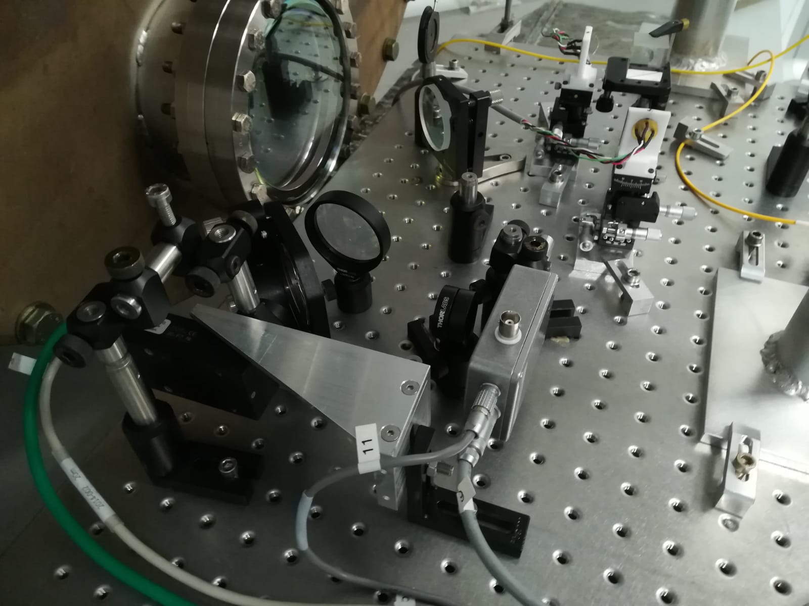
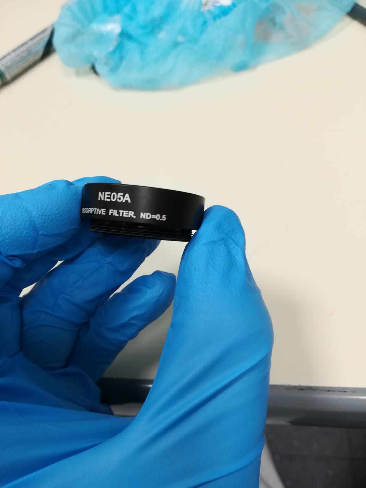
This afternoon we replaced the photodiode in transmission of the reference cavity (located on the external reference cavity bench) with the one prepared by Flavio (fig 1). We did this operation in LN3, with the RFC keeped in resonance but not locked, as suggested by Paolo.

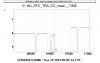
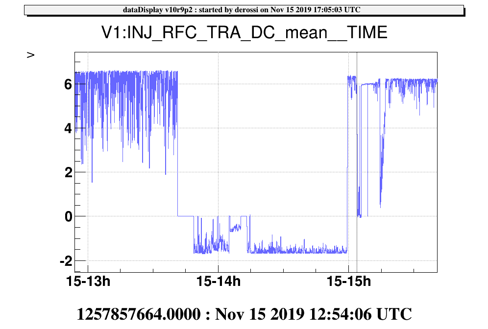
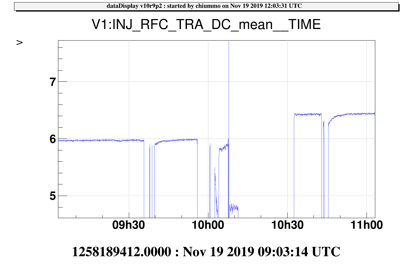
We then had to readjust the gain in Acl in order to recover the same amplitude voltage than before (plot 2) and we also loaded filter "flt_RFCunshape", prepared by Michal.

We finally could relock the ITF without any problems.

Images attached to this report
Comments to this report:
nocera - 10:31 Monday 18 November 2019 (47700) Print this report

The RFC-Tra monitor PD installed has been designed to be shot noise limited between 10 Hz and 1 kHz both with the current level of impinging power (estimated to be around 20 mW) and the future one (~40 mW).
The sensor used is a OSI Optoelectronics' PIN-6DI, whose Responsivity at 1064 nm is ~0.33A/W.
According to simulations, electronics noise is below shot noise by a factor that goes from 2 to 8 depending on power level and frequency.
The transimpedance is 666 ohm (to stay below ADC saturation, 10 V).
To make the shot noise level readable by the ADC used, whose noise floor is ~250nV/sqrt(Hz), a shaping filter having 1 zero at 1 Hz and a pole a 20 Hz has been added and both the design and the measured transfer function are visible in fig.1
The PD noise in dark conditions has been measured as well (fig.2)

Images attached to this comment
Non-image files attached to this comment
mwas - 10:36 Tuesday 19 November 2019 (47712) Print this report

Figure 1 shows the performance of the new photodiode. In purple is a time with no power on the photodiode, in brown with the RFC locked, and in blue with the RFC locked before photodiode change. The data between the two photodiodes is comparable because a digital gain of 3.8 was put in to have the same recorded DC voltage in the DAQ for the two photodiodes.

For the electronic noise, the ADC noise is nominally at 2.5e-7 V/rtHz, unshaping the signal lowers it by a factor 20 and applying the gain 3.8 increases it. So in total it is expected to be at 2.5e-7/20*3.8 = 4.8e-8 V/rtHz, slightly lower than what is measured at 6e-8 V/rtHz.

With light present the shot noise is at 1.2e-V/rtHz, which corresponds to a RIN of 2e-8 1/rtHz. This is much higher than I expected, and would be consistant with only 1mW detected by the photodiode instead of ~20mW. The explanation for it is two fold:

  • There is a neutral density filter in front of the photodiode, the absorption is not known, but given that the voltage output is a factor 4 lower than expected, we can guess it absorbs 75% of the power. The neutral density filter will be removed to increase the power, it should also lower the coupling of beam jitter, as neutral density filters create large couplings of beam jitter due to non uniform absoption, and absorption aging due to the beam passing through them.
  • The photodiode quantum efficiency is rather poor, with a responsitivity of 0.33 A/W whereas a perfect photodiode would have a responsitivity of 0.85 A/W, so the efficiency is only ~40%. During the discussion on the photodiode choice, it was known that the responsitivty is at 0.33 A/W, but I hadn't realized what is the meaning of that quantity, and that it translate to a low quantum efficiency.

This two combined could explain why the shot noise is a factor 4 higher than I expected.


Images attached to this comment
chiummo - 13:12 Tuesday 19 November 2019 (47714) Print this report

An optical density of about OD = 0.5 has been removed around 10:10 UTC before the newly installed RFC_TRA photodiode. The digital gain has been adjusted from -3.8 to -1.5 to roughly match the previous output and be compliant with the existing lock acquisition thresholds).

Images attached to this comment
nocera - 8:22 Wednesday 20 November 2019 (47730) Print this report

It is probably useful to mention explicitly the relationship between Responsivity (R) and quantum efficiency for future reference.

Real sensors are not ideal and their Responsivity is smaller than the ideal one, which turns out to be Rideal = 0.806 * lambda (with lambda in microns).
@ 1064 nm then Rideal = 0.858.
To get close to this, InGaAs sensors are used when it is required.
For less demanding applications, such as beam monitor and the like, usually Silicon PIN sensors are normally used.
Quantum efficiency is the ratio Rreal/Rideal.

Images attached to this comment
Search Help
×

Warning

×