Reports 1-1 of 1 Clear search Modify search
Detector Characterisation (Broadband noise)
ruggi - 14:09 Friday 15 November 2019 (47673) Print this report
Range variations and subtraction efficiency

In a period characterized by range variations from 49.5 Mpc to 51.5 Mpc (fig 1), a comparison between good and bad data has been performed. One evident difference is the effect of the subtractions: comparing hrec_raw and hrec in the bad case (fig 2) and in the good case (fig 3), in the second case the gap is larger. I am not expert of hrec to explain that; I can just give some more information.

fig 4: hrec_raw looks the same in the two cases; no additional noise seems the source of the sensitivity worsening

fig 5: no variation is visible in PRLC, but the coherence with hrec_raw (fig 6) is different.

fig 7: hrec after the subtraction, in the two different cases.

Images attached to this report
Comments to this report:
mwas - 15:26 Friday 15 November 2019 (47675) Print this report

From these figures we see that the noise in hrec_raw stays the same, but that its coherence with LSC_PRCL is decreased when the range is lower. As the noise subtraction are done in a linear fashion, a smaller coherence means it is less able to subtract the noise. In the 100Hz-1kHz band, the PRCL subtraction correspond to subtraction frequency noise coupling due to the arm assymetry (CMRF).

Figure 1 shows the trend of a few channels related to the CMRF. In Sc_BS_CMRF we can see that its mean value get closer to zero and that it fluctuate less. On the 1111Hz and 3345 frequency lines demodulated in DARM we can see that the line moves away from zero, as the magnitude get larger, and the phase stops flipping sign.

I see two potential explanation to the reduce coherence between PRCL and DARM (and hence not as efficient subtraction)

  1. The CMRF is fluctuating more at the beginning of the data stretch, as the subtraction takes the mean value over 500s to compute the coupling it is not able to subtract the CMRF contribution to the fluctuations
  2. The CMRF is close to zero as seen on the 1111Hz and 3345Hz lines in DARM, so the coupling is changing sign all the time. As the transfer function is a comple number at each frequency bin, the average around zero may give much worse result, than trying to make an average around a non zero value.

I don't think that explanation 2) is the right one, as everything is linear in the subtraction, so having a zero or non zero mean value should not make a difference, but I may be missing something here. To me explanation 1) is more likely, the arm assymetry is fluctuating more, hence the loss of coherence and the poorer subtraction. The only solution would be to find what is modulating the CMRF (probably some alignment signals), and do a bilinear subtraction. The easiest should be to study the sidebands of the 1111Hz and 3345Hz line to find what is modulating the coupling.

Figure 2 and 3 shows that the "wings" (due to coupling modulation) around the 1111Hz and 3345Hz line in DARM are smaller when the subtraction is working better.

Images attached to this comment
mwas, patricelli - 11:36 Wednesday 04 December 2019 (47852) Print this report

Barbara Patricelli has studied in more detailed how the frequency noise coupling is modulated, by looking for bilinear coupling using a few dozen other channels, during the time when the frequency noise subtraction was not working well.

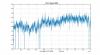
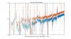
Figure 1 shows the most coherent contribution, which are mostly related to the position of PR and the beam pointing into the interferometre. The full list of channels ranked by coherencein each 10mHz frequency bin  is in the attached text file.

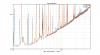
Figue 2 the coherence with B1p 56MHz I is more surprising, it could be due to the dark fringe offset itself or to the amplitude of the 56MHz sidebands. Comparing B1p 56MHz I  and B4 112Mhz mag, the coherence and projection is much higher for B1p 56MHz I, so the main driver here is not the change in the 56MHz amplitude but the carrier light itself. This means that the dark fringe offset is fluctuating, and that these fluctuation modulate the frequency noise coupling. The dark fringe offset could fluctuate due to fluctuation in the carrier gain in the PR cavity, or due to alignment fluctuation modulating the matching with the OMC.

In any case, the most coherence in the +/-200mHz range around the 1111Hz laser frequency line is with the ASC_PR_Y_CORR and ASC_PR_X_CORR channels. This would argue that the centering of the PR mirror plays an important role in modulating the frequency noise coupling, and that a better centering of the beam on the PR mirror could make the frequency noise coupling less depend on the PR mirror transversal position control.

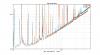
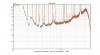
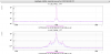
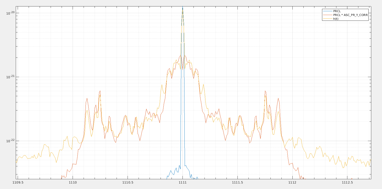
Figure 3 shows the region around 1111Hz for h(t), and a fitted projection of LSC_PRCL (out of loop frequency noise signal) and LSC_PRCL*ASC_PR_Y_CORR. LSC_PRCL can explain well the line at 1111Hz itself, and LSC_PRCL*ASC_PR_Y_CORR the wings in +/-1Hz band.

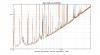
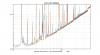
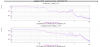
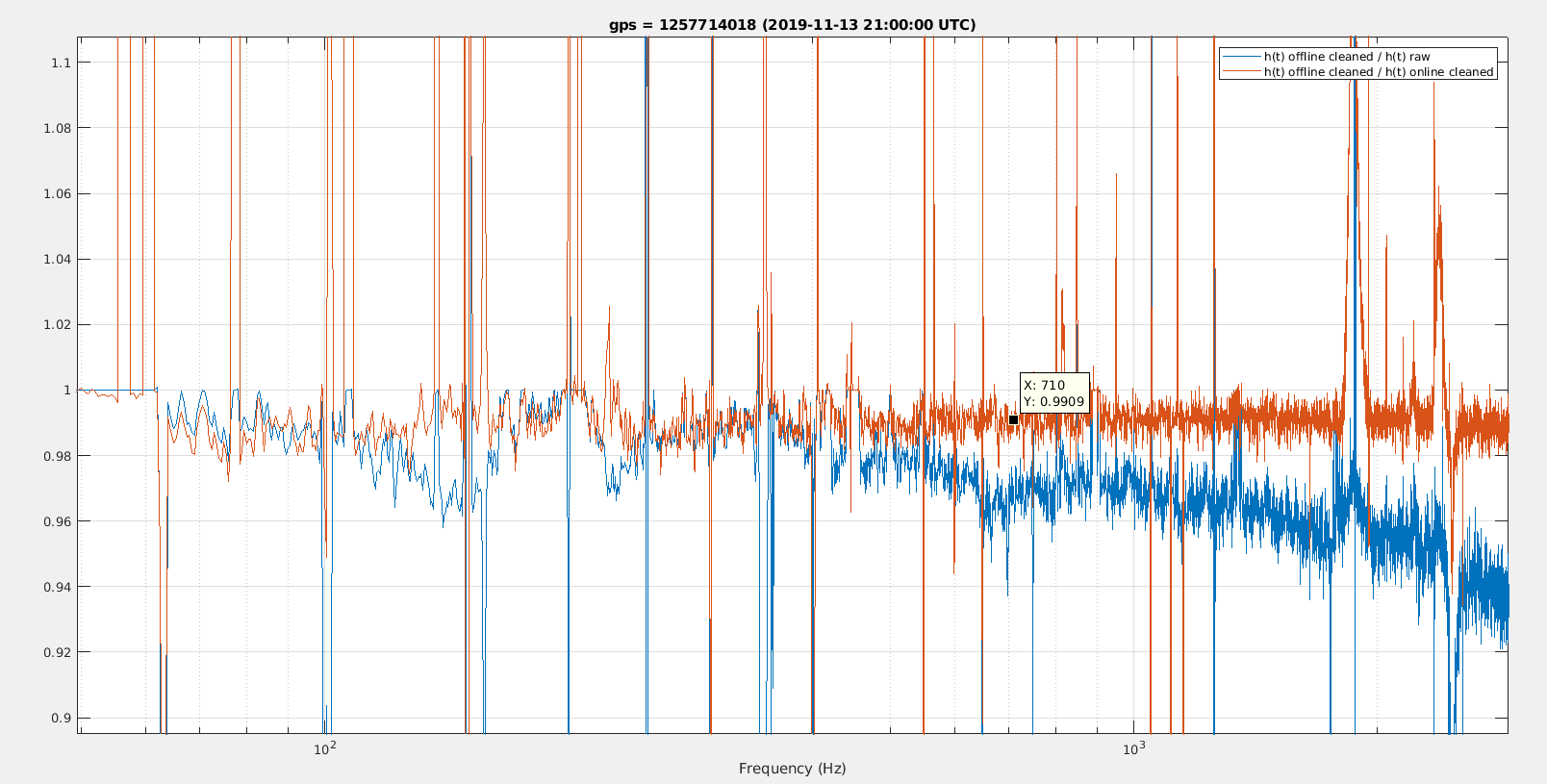
Figure 4 shows an attempt of doing a bilinear noise subtraction in h(t) using LSC_PRCL*ASC_PR_Y_CORR, the code to do that is very crude, but comparing the ASD of h(t) with this additional subtraction with h(t) with the online (linear) noise subtraction, we can find a improvement of ~1% (red line in the figure). So this modulated frequency noise coupling is a good candidate for explaining the 2Mpc sensitivity loss when the linear subtraction is not working well. But the bilinear noise subtraction (at least in this crude implementation) is not able to recover the sensitivity.

/users/mwas/calib/noiseSubtraction_20191113/noiseSubtractionBilinear.m

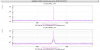
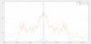
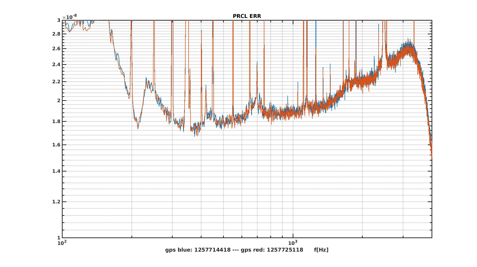
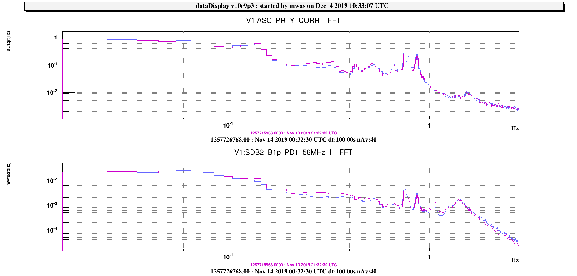
Figure 5, note that between the bad time (purple) and good time (blue) the fluctuations of ASC_PR_Y_CORR and B1p 56MHz I have reduced only by 20% and only around 300mHz. So the main driver are not the position fluctuations themselves, but something else (maybe some slow trend in global alignment).

Images attached to this comment
Non-image files attached to this comment
Search Help
×

Warning

×