Reports 1-1 of 1 Clear search Modify search
AdV-DET (Commissioning)
mwas - 22:21 Sunday 27 October 2019 (47424) Print this report
SDB1 alignment offset impact

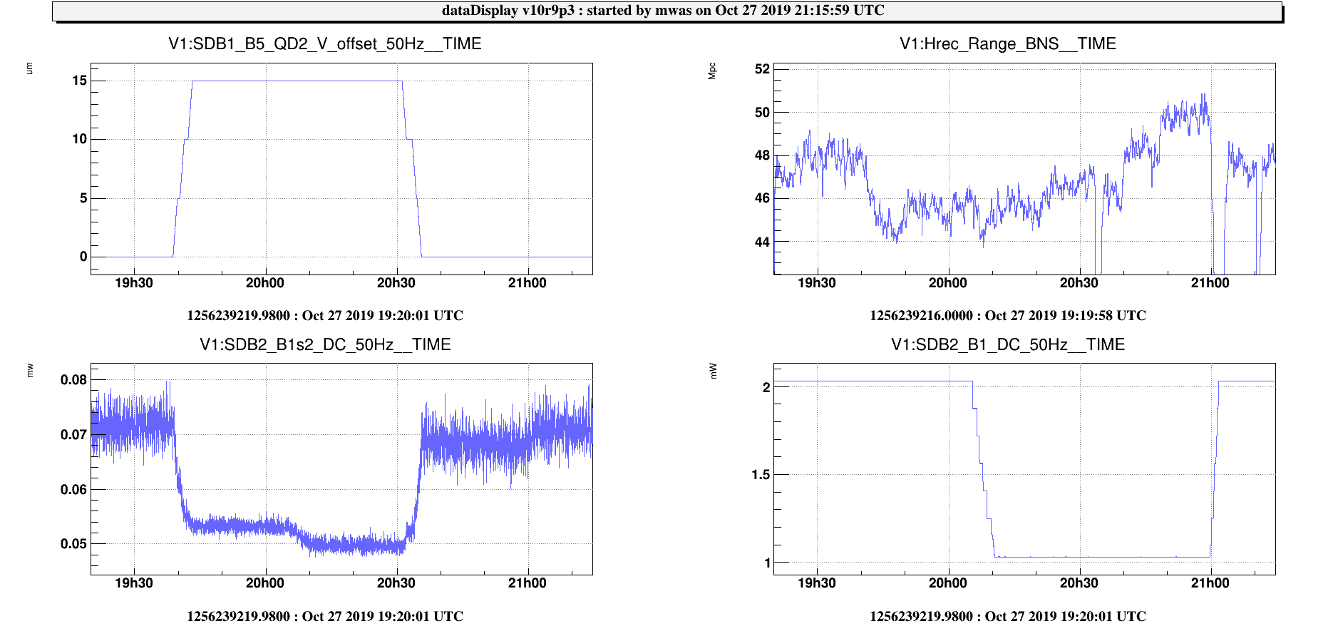
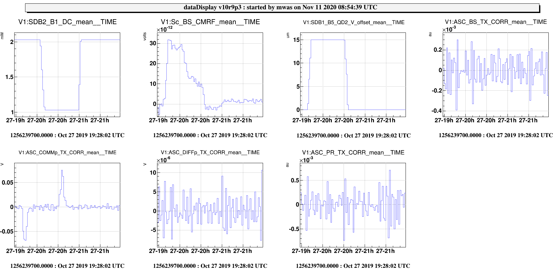
Took data to better explore the impact of SDB1 angular offset on sensitivity

~19:39 offset on SDB1_B5_QD2_V = +5

~19:40 offset on SDB1_B5_QD2_V = +10

~19:42 offset on SDB1_B5_QD2_V = +15

19:44 UTC (20min) data with +15 vertical offset, B1s2_DC power much smaller at ~0.053mW instead of ~0.072mW, but range drops by 3Mpc

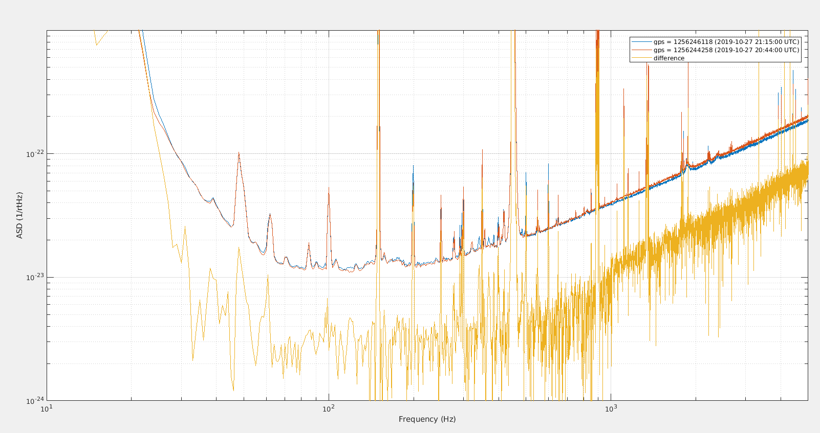
20:11 UTC (20min) +15 vertical offset, and dark fringe offset reduced, 1mW on B1_DC (instead of 2mW), DARM UGF kept at ~97, no impact on range, B1s2 reduced from 0.053mW to 0.0495mW. First 5-10min of these data is with h(t) wrong, as the calibration did not catchup with the change in dark fringe offset

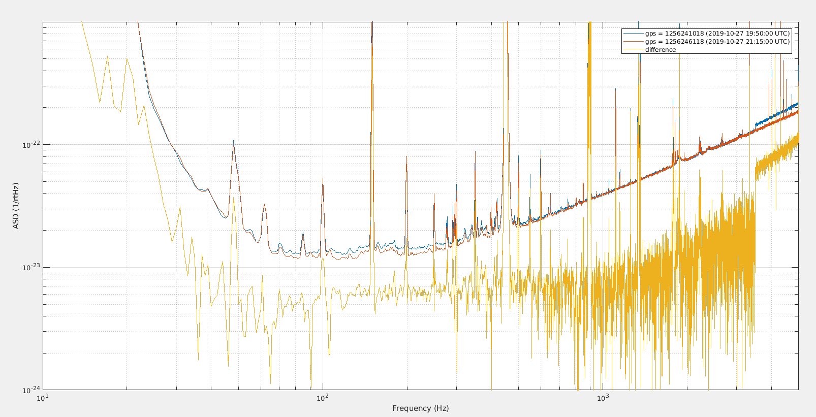
20:37 UTC (20min) no SDB1 offset, dark fringe reduced, 1mW on B1_DC

21:02 UTC, no SDB1 offset, dark fringe at standard value of ~2mW on B1_DC, h(t) up to date 5-10 minutes after that

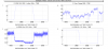
Data will be analyzed later, but a quick look (figure 1) shows that with a dark fringe offset of 1mW and no offset on SDB1 angular control the range is better by 2 Mpc (presumably due to lower flat noise and photodiode 1/sqrt(f) flicker noise). For the moment left the standard configuration for the night (2mW on each B1 PD).


Images attached to this report
Comments to this report:
Allocca - 10:36 Monday 28 October 2019 (47427) Print this report

I've plotted the B1 and B1s2 cameras in logscale and zoomed the coloraxis for B1, which saturates the central part of the beam, but shows better the difference of HOMs between GPS 1) and 3).

Figure 1) is the configuration with offset, and 3) is without offset. In figure 1) a HOM is slightly visible on B1, while it's not visible in figure 3). A difference is also visible on B1s2, where the HOM slightly changes orientation and power.

Images attached to this comment
mwas - 11:35 Monday 28 October 2019 (47426) Print this report

Correction. There was previously an inversion between 2) and 4) in the table below. There are 4 reference interesting times, with 15 minutes of data each:

  1. 19:50:00 UTC - angular offset, 2mW on B1
  2. 20:15:00 UTC  - angular offset, 1mW on B1
  3. 21:15:00 UTC - no angular offset, 2mW on B1
  4. 20:44:00 UTC - no angular offset, 1mW on B1

Figure 1. Comparing 3) and 4) we can measure the power dependent "flat noise" in normal conditions, it corresponds to a difference of ~3.5e-23 @200Hz, so a total noise of 5.0e-23 assuming a scaling with square root of power, which is about the same as the estimate from 6 months ago of 6e-23 @200Hz.

Figure 2. Comparing 1) and 2) we can have the same measure when the angular offset is present. It corresponds to a difference of ~5e-23 @200Hz, so a total noise of 7.1e-23 assuming a scaling with square root of power.

Figure 3. Comparing 1) and 3) we have a measure of how much the "flat noise" increase due to the angular offset when there is 2mW on B1. It corresponds to a difference of ~6e-23 @200Hz.

It is not clear if the additional flat noise due to the angular noise, is of the same origin as the normal flat noise without the angular offset. But both increase with dark fringe offset (the B1 power). Unfortunately I forgot to increase the B1 and B1s2 camera gains, to see if a high order mode appears when adding an angular offset into SDB1.

In any case, the OMC is clearly misaligned when there is no offset on SDB1 (both compared to the carrier and to the 56MHz sideband), we could try to realign with picomotors in order to have it aligned without adding offsets into SDB1 angular position. This could also disentangle whether the additonal noise is due to SDB1 alignment or to OMC alignment.

Images attached to this comment
mwas - 9:57 Wednesday 11 November 2020 (49897) Print this report

The test of changing the dark fringe offset and the SDB1 alignment provides also some information on the frequency noise coupling (CMRF).

Figure 1. With the angular offset added to SDB1 the frequency noise coupling increases by a factor ~10. Reducing the dark fringe offset reduces that coupling by a factor 2. So the coupling is not due to the misalingment causing more junk light passing through the OMC, and that junk light carrying frequency noise, as in that case the coupling should increase with lower dark fringe offset. Without the SDB1 alignment offset the CMRF still changes when the dark fringe offset is changed, but about 5 times less. This could actually be used to define an optimum for the SDB1 alignment offset, find the offset which makes the CMRF independent of the dark fringe offset.

Figure 2. Note that the change in CMRF may not be due to the misalignment on SDB1 itself, but that moving SDB1 acts on the COMMp degree of freedom of the interferometer, and changes the interferometer alignment working point.

Images attached to this comment
Search Help
×

Warning

×