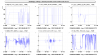
Figure 1. Shows the RFC error signal spectrum from Sep 7 in blue, and in red it shows roughly what it would need to be to compliant with the OMC requirement on the absolute laser frequency stability. The red curve is obtain from the blue just by using a 1/F shaped loop (pure integrator) with a unity gain at 2Hz.
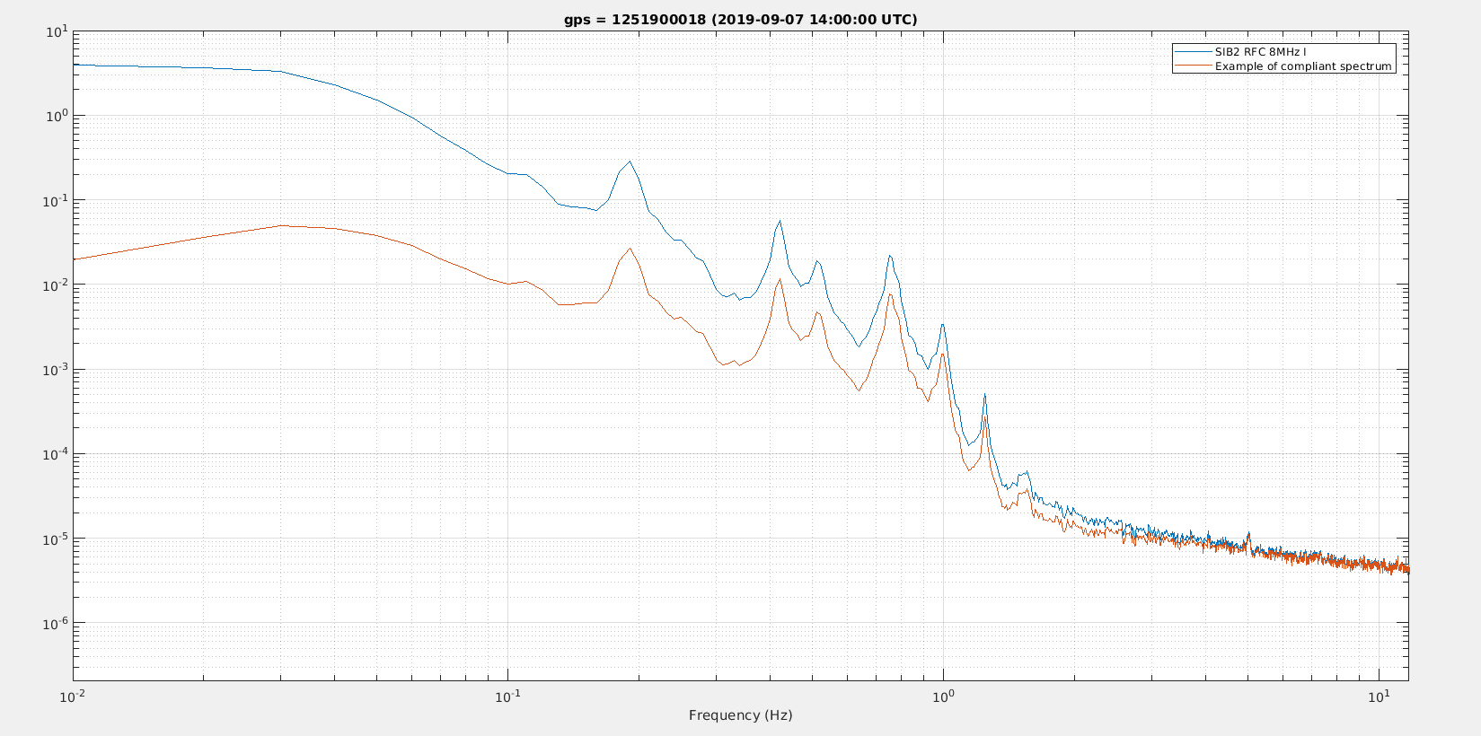
Figure 2 shows the perspective from the OMC error signal point of view.
- In dark blue is the OMC error signal, note that error signal has a large sensing noise as the OMC length dither was reduced by a factor 10 just before O3 as a precaution against non linear noise couplings
- In red is the RMS of that error signal, it is at 1.3e-11 m, while the requirement for O4 and for the Advanced Virgo design is 6e-13m
- In yellow is the scaled RFC error signal multiplied by frequency. It needs to be multiplied by F, as the OMC tries to follow the CARM motion, and has a filter with roughly a 1/F shape at 0.1-1Hz frequencies. With that transformation the RFC error signal matches roughly what the OMC is seeing.
- In purple is the corresponding RMS, which is dominated by the bump at ~30mHz, but with also some contribution from the lines between 0.1Hz and 1Hz.
- Green is same as yellow, but with a filter with 1/F shape and unity gain at 2Hz applied
- In light blue is the corresponding RMS, the different lines have a similar order magnitude contribution, and add up to a 5.3e-13m RMS
Note that slow CARM loop implemented in January 2017, was compliant and leading to an OMC length RMS of 4e-13m. But this was a computed not a measured quantity, so it assumes all the calibration factors to convert from RFC error signal to OMC error signal are correct.
Script in /users/mwas/OMC/OMCspecCARM_20191016


