
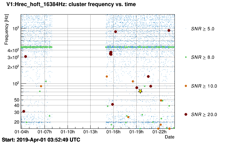
Omicron scan shows nothing outside of PSL/ INJ. Reference Cavity quads with strongest response.
Omicron report output found here
Nothing really clear or evident from our side.
Investigation in progress...
These glitches have been caught by the online flag V1:DQ_Omicron_VETO_GENERIC_PSL_PMC_TRA_AC_2019-03-30-pstab: see the before/after plots when applying the veto
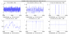
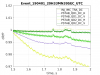
plot 1, 221 shows the power after the IMC (belong to PSTAB syst). PD2 is used as the error signal of PSTAB, PD1 is used as the out-of-loop monitor. PD2_AC_MONIT and PD1_AC are converted in W at the neoVAN location.
PD2 & PD1 calibrations : K_PD2 & K_PD1
K_PD2 = 86/(1.32/50)/6732/10
K_PD1 = 86/(1.32/50)/6732
(86 W at neoVAN, 1.32 V dc at PD2 & PD1, 50 & 6732 ohm for DC & AC channels of PDs, gain x10 for PD2 path specifically provided by ramaputo)
Rem.: on all the signals we have removed the lines at 50/100/150/350/1151 Hz to make them more readable. Mostly needed for HF_CORR
- PSTAB makes the job of keeping the error signal (PD2) close to zero (plot 221)
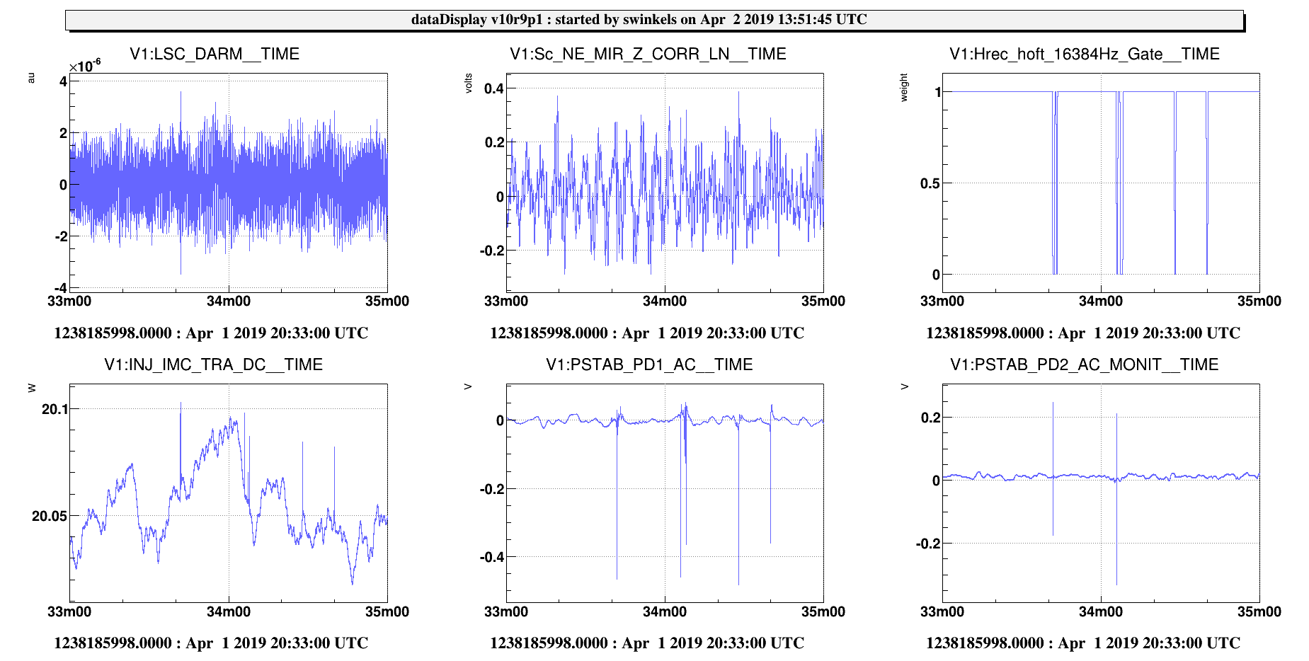
- "slow" drift of 0.2 W within 1 ms before saturation on PD1 (plot 221)
- likely too fast to be related to IMC alignment
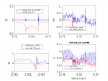
- nothing (related to the above-mentionned drift) visible on PSTAB_HF_CORR nor on PMC_TRA_AC (the latter should mimic PSTAB_HF_CORR), plot 222
- zoom in plot 223, the timing shift is likely due to the PMC_TRA_AC sampling limitation (20 kHz)?
- rem.: on plot 222 HF_CORR is more noisy than PMC_TRA_AC. It means HF_CORR mainly compensates for the neoVAN RIN (right upstream to the PMC)
- no clue why it is visible on PD1 and not on PD2. All happens as if there were some drift through the perturb input of the PSTAB_rampauto. We have made installed the monitoring (fast) of the error signal before and after the perturbation input (30/04/19):
-> PSTAB_PD2_AC_MONIT_FS (after the perturb, acquired 800 kHz, already existing at 20kHz)
-> PSTAB_PD2_AC_PRE_FS (before the perturb, acquired 800 kHz, new signal)
Conclusion:
lets wait and catch another equivalent glitch (only PSTAB related) and see PD2_AC_PRE & POST signals
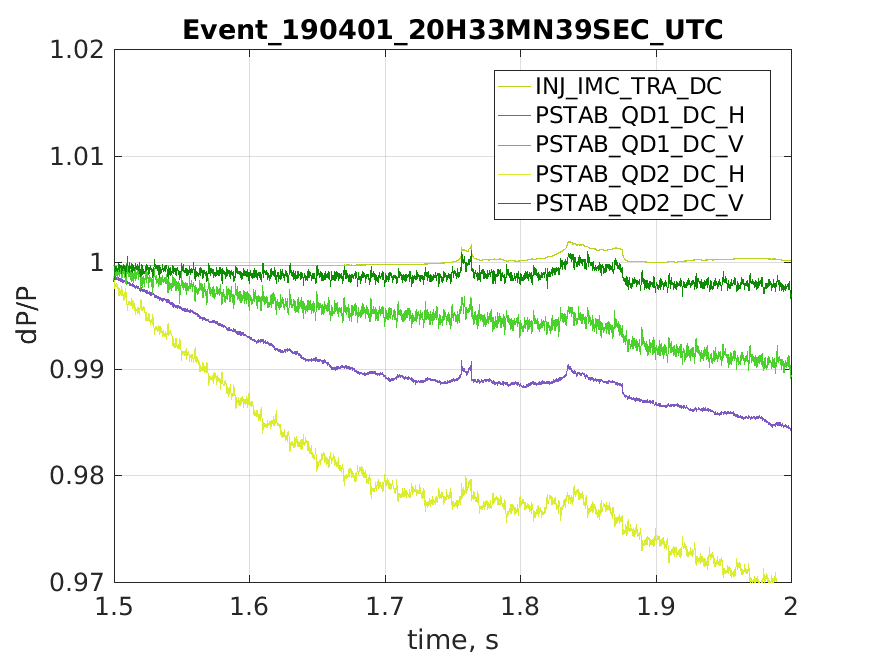
with the plot
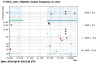
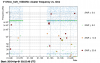
The plot shows the PSTAB Quadrant error signals normalized by their DC value. The time zoom refers to the event visible in subplot 221 of entry 45807 .
The quadrant error signal shows the RIN of the beam (through the residual offset) and the information related to beam alignement.
We notice that the glitch is visible on all signals and with the same amplitude as in IMC_TRA. This means that any feature due to true misalignment would be a small fraction of IMC_TRA RIN, that is much less than 0,2%
We know the calibration of the Quadrant is ~ 6000V/m (see 34112). We deduce a majoration of the beam misalignment at the quadrant level of << 0,2% / 6000 = 3e-7 m.
We deduce a possible induced RIN at the PSTAB PD1 & PD2 photodiodes being less than 3e-7 * K = 3e-7. Where K is the coupling factor RIN versus beam shift on the considered PD assuming the non-homogneity of the PDs.
Since this effect is much smaller with what observed (0.2%) -> a possibe glitch on the beam alignement can't explain the observed glitch