On thursday morning, we vented the SDB2 mini-tower to perform several actions on the bench.
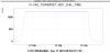
The venting started around 09:00 UTC and the pumping started around 14:15 UTC, in total the mini-tower was in air for about 5 hours and a half, 6 hours (figure 1).
We perform the following actions on the bench :
1. Release of the torque of the suspension wire.
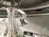
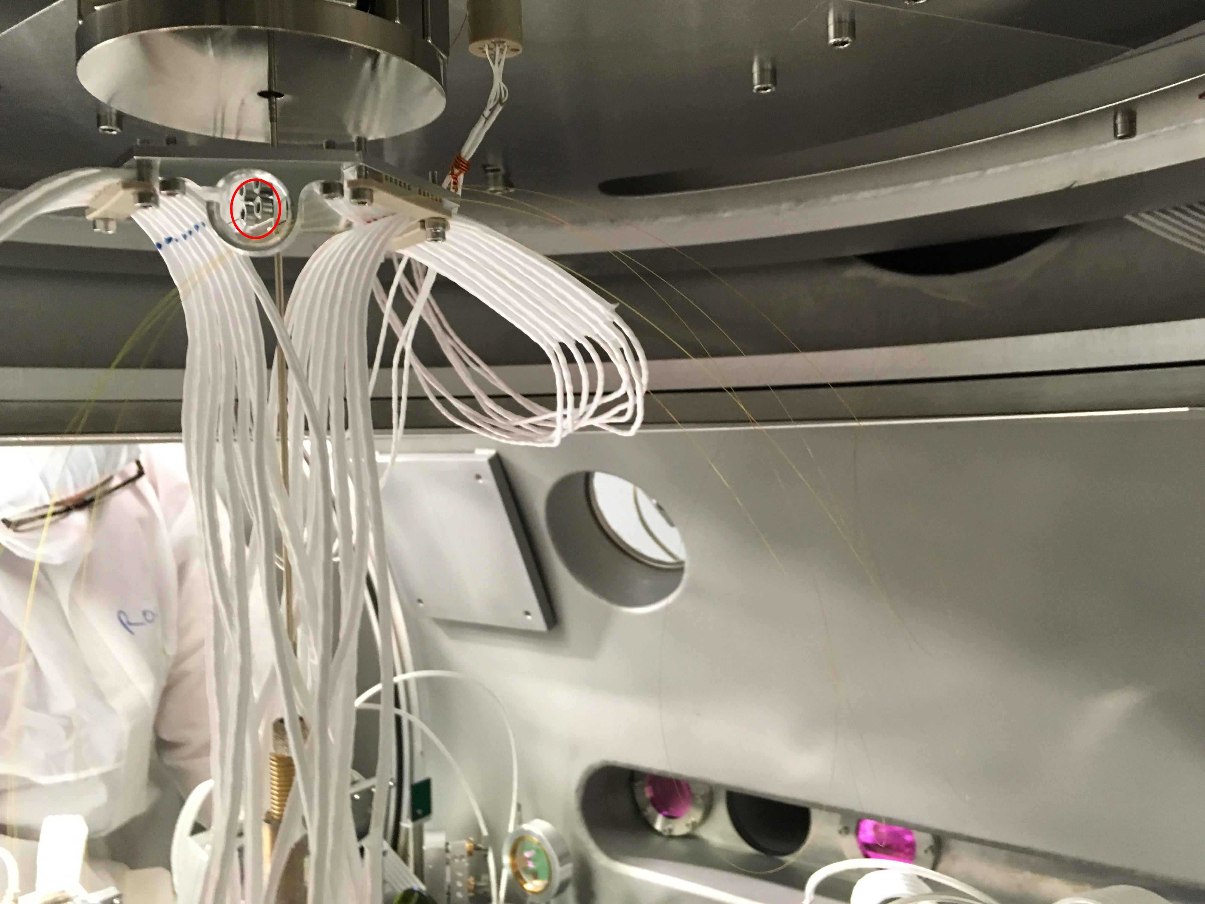
To release the torque of the wire connecting the mSAS and the bench, the idea was to untighten the cable disk that is supporting the cables and fiber coming from above (figure 2) and then tighten it again in a better situation.
This is a very delicate operation, because the 2 screws (circled in red in figure 2) are very difficult to access and because of the bare fiber running along the wire.
So the screws were untighten gently in steps to see the effect on the bench free position, ideally the bench should settle in a position were the bench is not touching any stops At some points we thought we had improve the situation. Also we closed the angular control in different conditions in order to see the correction sent to the TY degree of freedom (which is more or less a measurement of the torque of the wire). At some points it appears to be lower than usual. We also try to release the torque by pulling on the cable disk when it was tighten to the wire.
After some trials, we stopped and blocked the bench for other activities. Before it was blocked the correction in TY was close to 0 V. After the end of the other activities we released the bench and checked the correction sent in TY to control the bench, it was around 1 V and we tried to act on the wire, we managed to put the correction to around 0.5 V. Later in the afternoon after the mini-tower was put back in vacuum, I closed the angular loops and found that the correction in TY was between 0.5 and 0.6 V.
Finally this morning, Alessandro Bertolini put the bench back in position and closed the angular loop, now the correction sent to the TY degree of freedom is about -0.05 V whereas it was 1.5 V before.
So it seems that we have improved the situation even if we did so a bit blindly.
2. Calibration of B1p_PD1 and B1p_PD2.
We installed a LED in front of the two photodiodes successively to calibrate the photodiodes, see dedicated entry 44428.
3. Swap of B1 beam-splitters.
Finally, we swapped the two beam-splitters in front of the two photodiodes.
The goal is to have 99.9% of the power on B1p_PD2 instead of 50% on each photodiodes.
Doing that we realized that the 50/50 splitter (W205) was not very clean so we put first contact on it and installed a spare (W206) temporarily in front of B1_PD1.
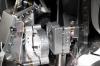
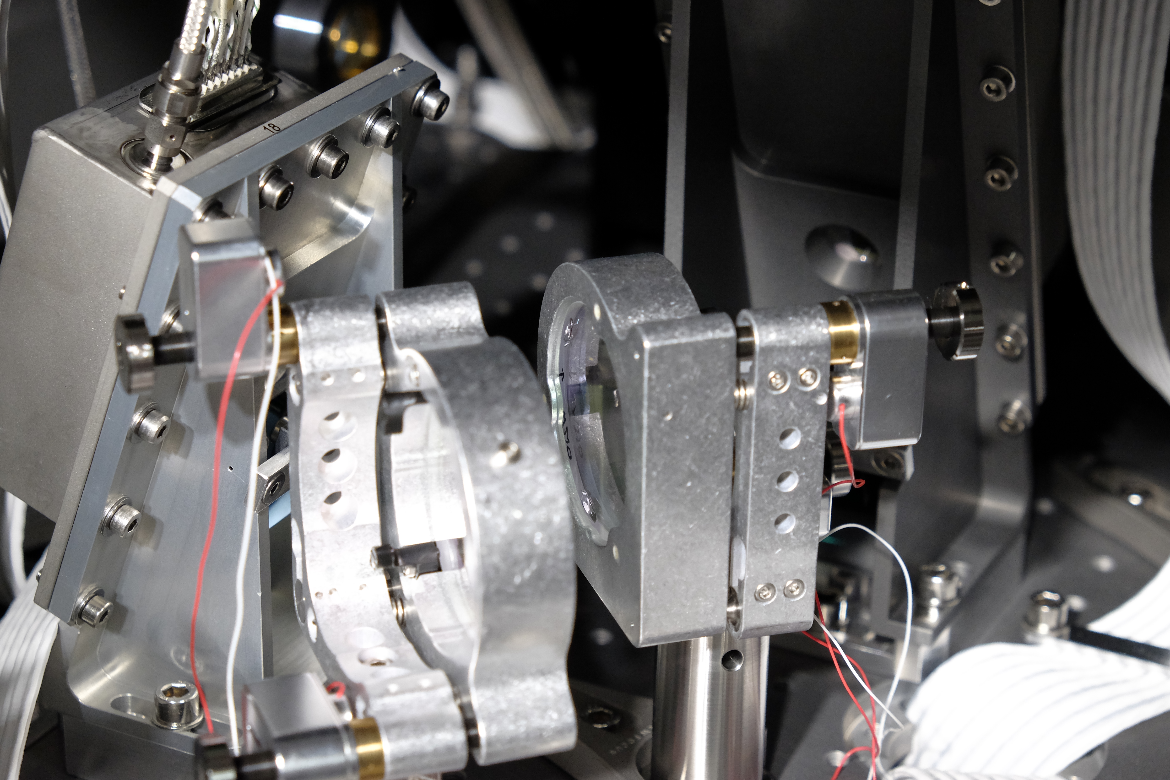
We also realized that the 99.9 % mirror (HR, W210) was mounted backward (the beam was going through the AR surface and substrate before hitting the HR surface), see figure 3, the arrow on the side of the mirror indicates the HR surface. This HR mirror (W210) has been put in front of B1_PD2.
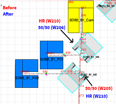
Figure 4 summarizes the swap of the splitters on B1 beam path.
