Reports 1-1 of 1 Clear search Modify search
AdV-ISC (Commissioning up to first full interferometer lock)
mantovani, casanueva, tacca - 12:11 Tuesday 13 November 2018 (43551) Print this report
ITF working point vs OMC working point

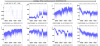
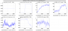
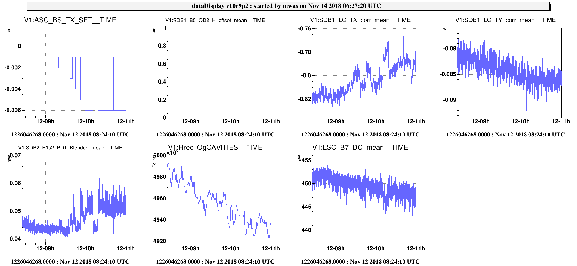
As it has been already seen the range is strongly correlated with the B1s2 PD1 blended signal. Using the scan on the DIFFp TX dof performed yesterday it is visible that the optimal working point for the ITF and the OMC alignment are different, see Figure 1. The optimal working point for the DIFFp TX is the one which minimizes the B1p DC, wp = 0, while the one which gives the highest BNS range (which minimizes the B1s2 blended signal) is 0.1.

This could be due to a misalignment of the OMCs with respect to the ITF, to be checked.

Images attached to this report
Comments to this report:
mwas - 8:20 Wednesday 14 November 2018 (43569) Print this report
The power on B1s2 and the OMC alignment are most likely not directly related.
The power on B1s2 measures the amount of 56MHz TEM01 leaking through OMC1, the OMC alignment should be to maximize the carrier TEM00 transmission.
A good measure of OMC alignment on the carrier is the ITF optical gain divided by the power stored in the arms.

Figure 1, shows that during the changes in BS TX set point, there was no correlated change in ITF optical gain, only a gradual decrease in gain by 1% due to the decrease in power stored in the arms by 1%.
The changes in BS TX set point, are compensated by tilting the SDB1 bench, as visible in the SDB1 TX correction, which keeps the beam aligned on the OMC.

Figure 2, shows that the changes in BS TX set point have a clear impact on the overlap between carrier and 56MHz. So it seems that the BS TX set points misaligns the 56MHz with regard to the carrier, which could be causing more 56MHz TEM01 through OMC1.

It is likely that several actuator set points (alignment and maybe DAS) need to be changed together to find a working point optimal for CMRF, B1p power fluctuations and 56MHz passing through OMC1 (B1s2 power).

Last night attempts at exploring the impact of SDB1 (and OMC) alignment were hampered by ITF lock stability
Figure 3, shows the single change we had the time to make. Changing the SDB1 alignment set point, caused the optical gain to drop by 1%.
Note that the optical gain measurement has a large delay, as it is computed using a median of calibration lines height over several minutes.
A faster monitor of OMC carrier throughput is being investigated to help with these measurements.
Images attached to this comment
Search Help
×

Warning

×