* took data with different DARM gains, and with only 1 B1 PD in loop, data to be further analyzed
* aligned OMC1 on NI single bounce beam
* mode mismatch is dominated by astigmatism
Found ITF unlocked, it seems that the INJ_MAIN metatron stalled after the unlock around 1:00 UTC.
Retrying the locked worked fine, Fmod err tuning and RFC scan took 5 minutes, but the rest of the lock was rather smooth.
07:03 UTC (2min) reference time a few minutes after full relock
07:06 UTC (3min) set B1_PD_BALANCE to 1.0 (using only B1 PD1 for DARM control)
07:10 UTC (3min) set B1_PD_BALANCE to 0.0 (using only B1 PD2 for DARM control)
07:14 UTC (3min) set B1_PD_BALANCE back to the nominal value 0.5054
Enabled DARM UGF servo, used to reduce DARM UGF from 105 to 80, and then disabled the servo
07:20 UTC (16min) DARM UGF around 81
Enabled DARM UGF servo, used to reduce DARM UGF from 80 to 60, and then disabled the servo
07:40 UTC (15min) DARM UGF around 60
07:56 UTC DARM UGF around 60, B1_PD_BALANCE at 1.0, ITF unlocked 20s after switching to B1 PD1 only
~08:27 UTC enabled SDB1 picomotors
checked if comparing DARM line height between B1s1 and B1s2 is useful as an OMC alignment signal (moved only OMC1 TY), it seem usable if OMC1 is controled with Peltier and PZT.
relocked and reduce DARM UGF using servo
08:52 UTC (15min) DARM UGF around 50
09:08 UTC (15min) DARM UGF around 50, B1 PD BALANCE at 1.0
intentionally unlock ITF, misaligned WI, WE, NE
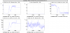
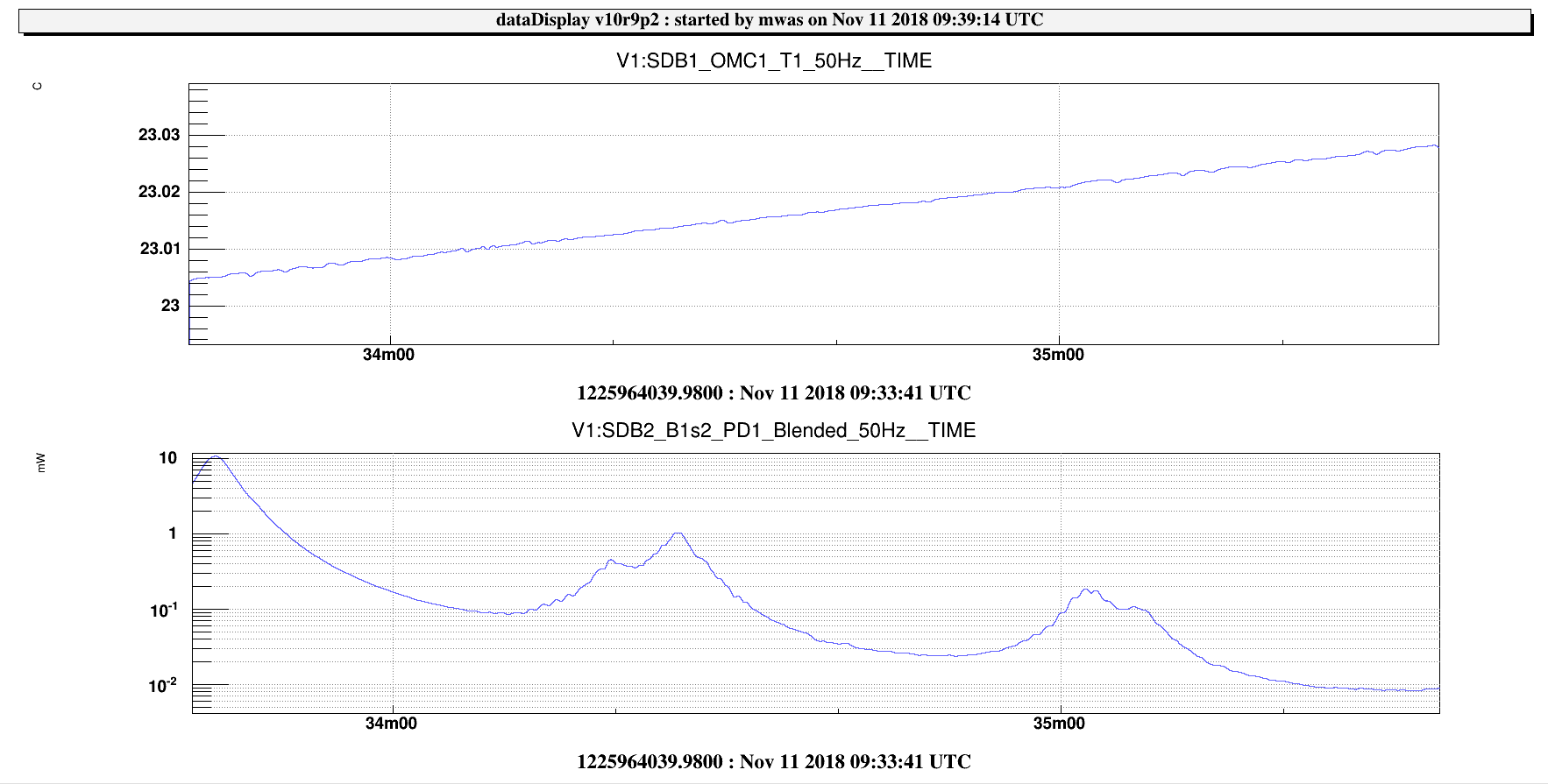
09:32 UTC (3min) slow OMC scan to check alignment and mode mismatch, quite bad OMC alignment Figure 1, ~8% misalignment
Reduced the B1x_f1_i_DC2n_err by a factor 100, the new automation of OMC loop gain has not been checked for this error signal.
Enabled SDB1 picomotors. Realigned OMC1 in TX and TY.
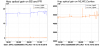
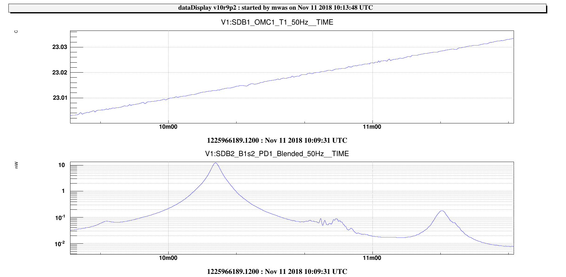
10:09:00 UTC (3min) OMC1 scan, Figure 2, <1% misalignment, ~1.5% mode mismatch, mode mismatch looks like astigmatism. Figure 3, shape of order 2 mode
by the way, OMC loop gain automatic adjustment works, could lock on order 2 mode by just changing the locking trigger.
Moved L2 vertically by 1600 steps, but there was no visible impact, so undid the movement.
Relocking and switched of SDB1 picomotors
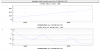
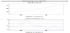
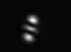
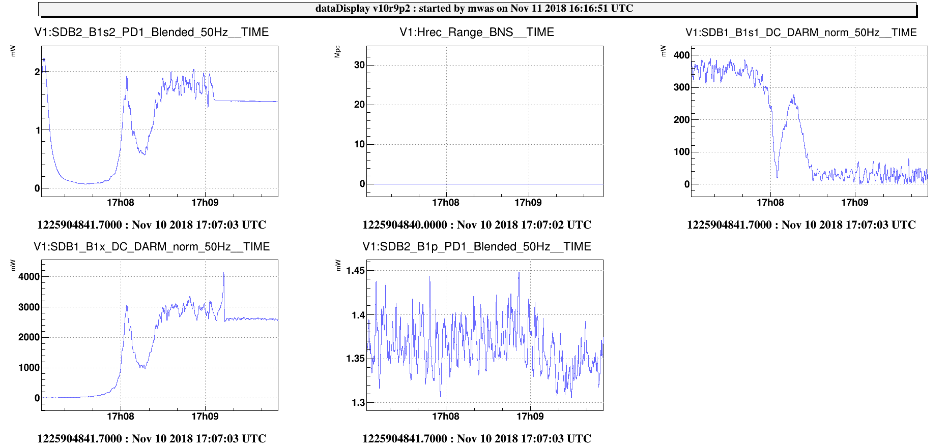
Figure 1 shows the OMC1 lock acquisition after alignment tuning. The height of the DARM line in reflection of the OMC (B1s1_DC_DARM_mag) drops from 350 to 50 when locking.
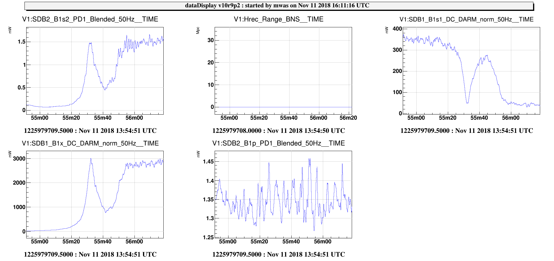
Figure 2 shows the same before the OMC alignment tuning, the height of the DARM line in reflection drops more from 350 to 20 on average (but with fluctuations between 0 and 50).
So on the basis of the amount of DARM line after alignment the situation looks worse.
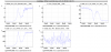
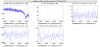
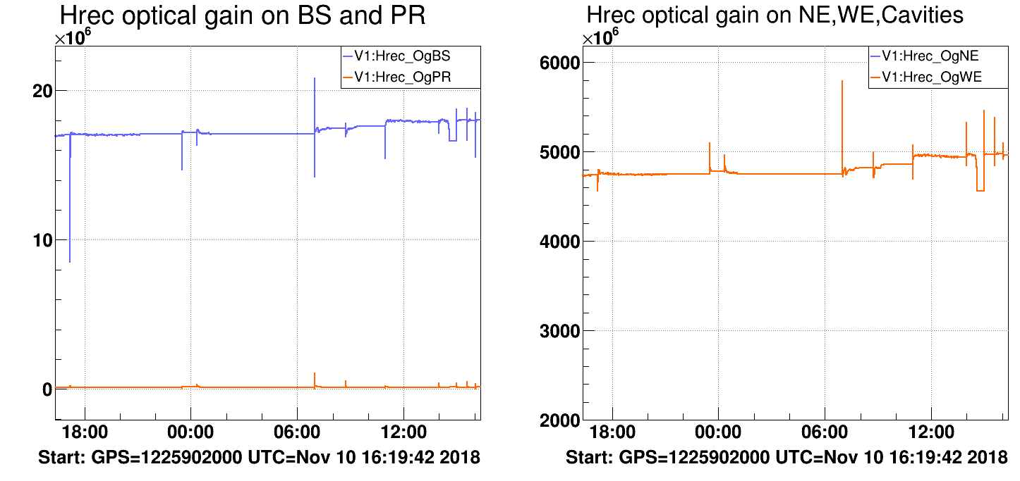
Figure 3, however when looking at the optical gain measured in Hrec, it seems to have improved by ~4%.
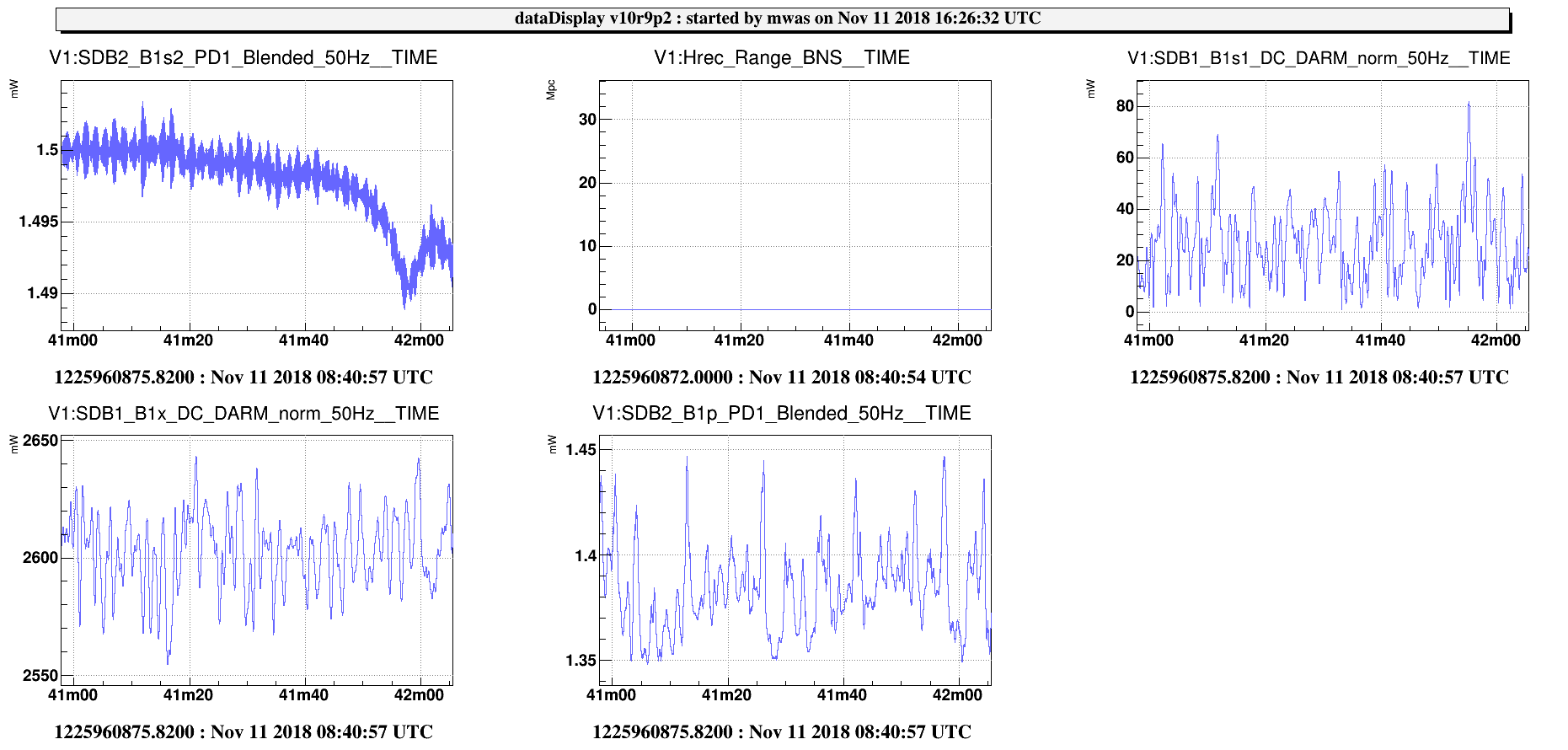
Figure 4, OMC1 locked, DC read-out before alignment tuning, the DARM line in B1s1 is around 30, and in B1x around 2600
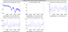
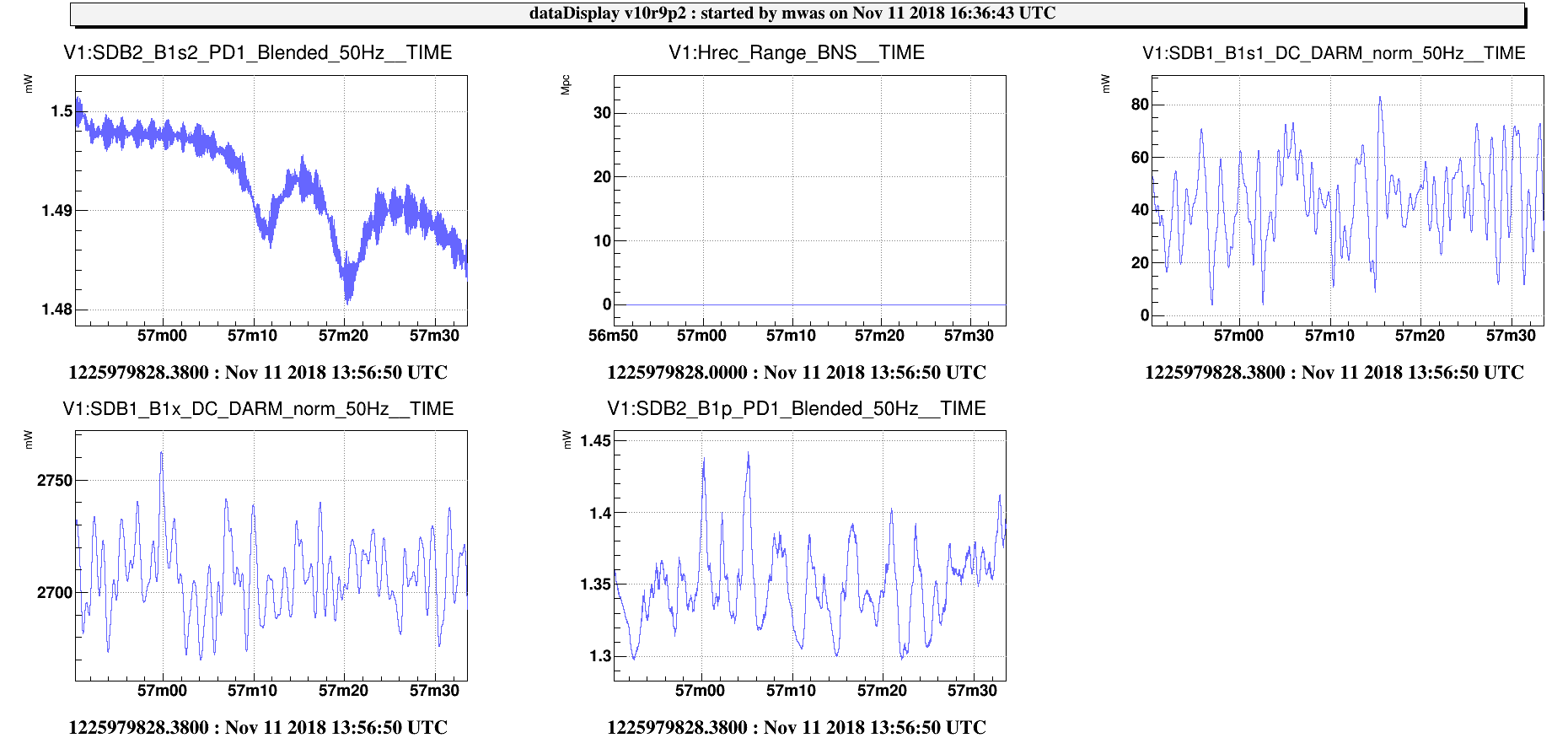
Figure 5, OMC1 locked, DC read-out after alignment tuning, the DARM line in B1s1 is around 40 (so seems worse) and in B1x around 2700 (so 4% better like the optical gain in Hrec)
More thinking and investigations will be needed to understand what is the right figure of merit for OMC1 alignment in dark fringe.
A first step would be to repeat this test with a higher DARM line modulation, to check if the height measure in B1s1 is not just limited by the line SNR.
So the result are consistent with the OMC alignment being actually improved in dark fringe as much as on single bounce, and it is just the height of the DARM line in the OMC1 reflected light that we don't understand.
The power on the B1 photodiodes can be written as
P_B1 = A L^2
where L is the dark fringe offset and A is a normalization that includes power in the arms, detection losses, etc.
The optical gain is the derivative of this
OG = 2 A L
Given that we keep the B1 power constant the dark fringe offset is
L = sqrt(P_B1/A)
which makes the optical gain proportional to the square root of the detection efficiency
OG = 2 sqrt(P_B1) sqrt(A)