Today we worked on the improvement of the alignment scheme:
-
we implemented a different scheme with respect to the past, in order to close the COMMp loop and not have it interfere with the galvo loop of the B5_QD2 sensor:
- during lock acquisition, we set a relatively high gain for the galvo loop just before re-enabling it (currently, 1e-2 with proper sign for V/H);
- with the galvo properly in place we can close the usual PR (full bandwidth) and BS (drift control) loops;
- once we ask OMC1 to lock, we get the current values of SDB2_B5_QD2_GALVO_[V,H]_CORR, and set them as offsets to the galvo themselves, using a slow ramp (60 s); concurrently, we decrease of a factor 100 the gains for the galvo loop, in order basically to discharge the DC of the loop and fix it in place;
- once we get to LOW_NOISE_3 we engage the COMMp loop using the usual DC signals with no offsets;
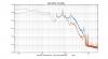
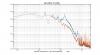
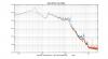
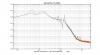
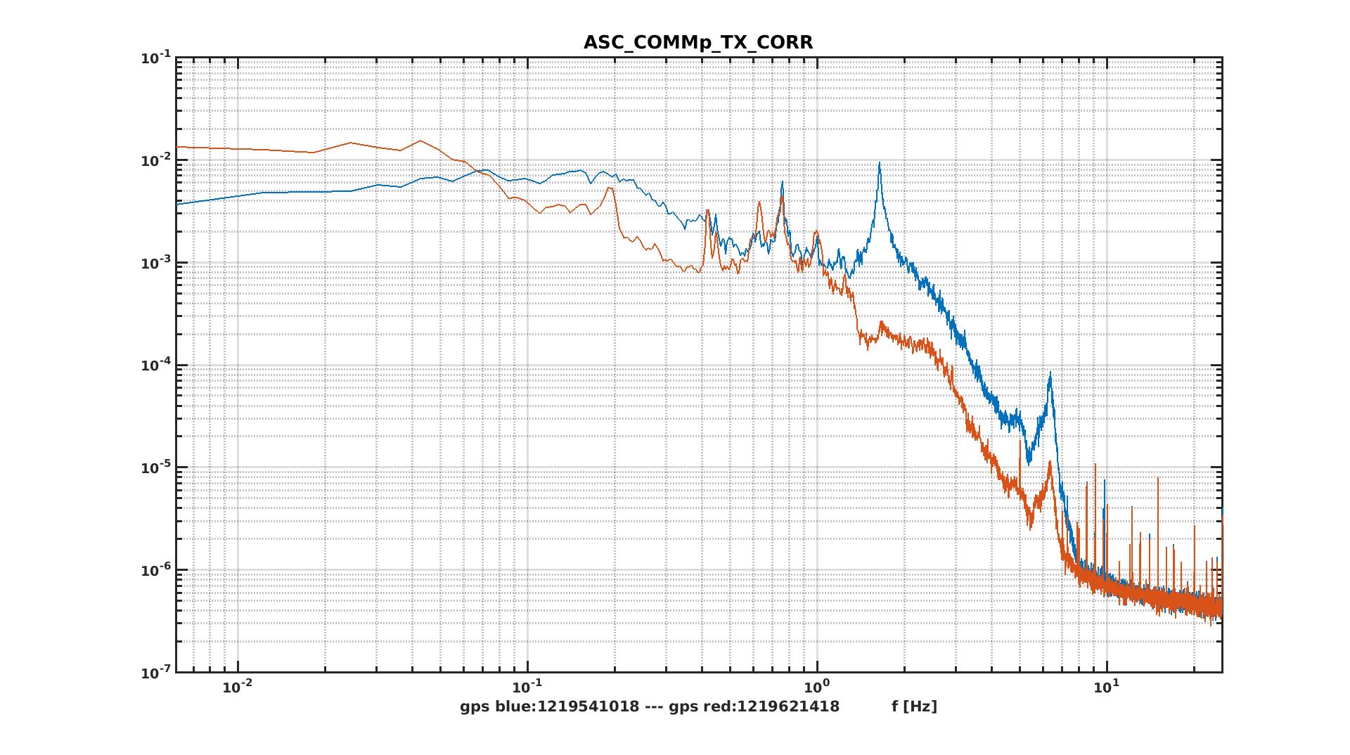
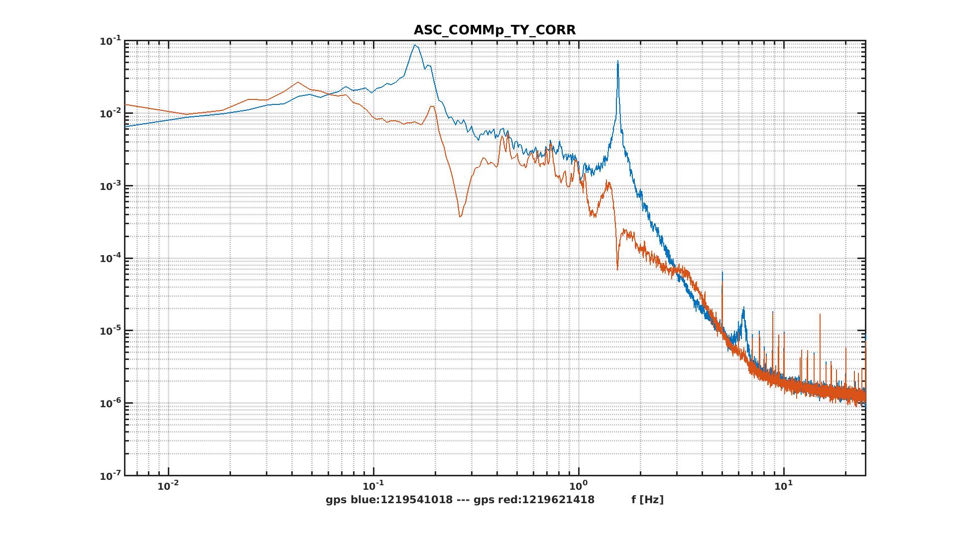
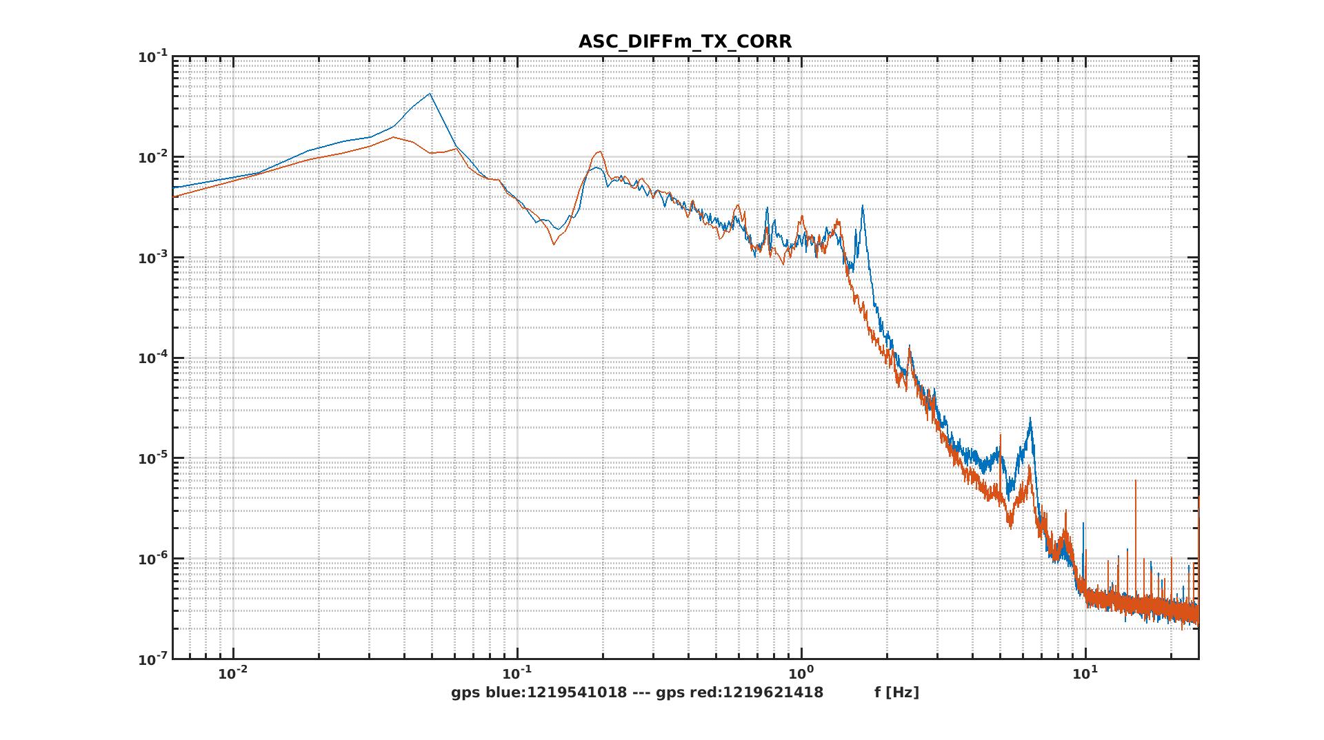
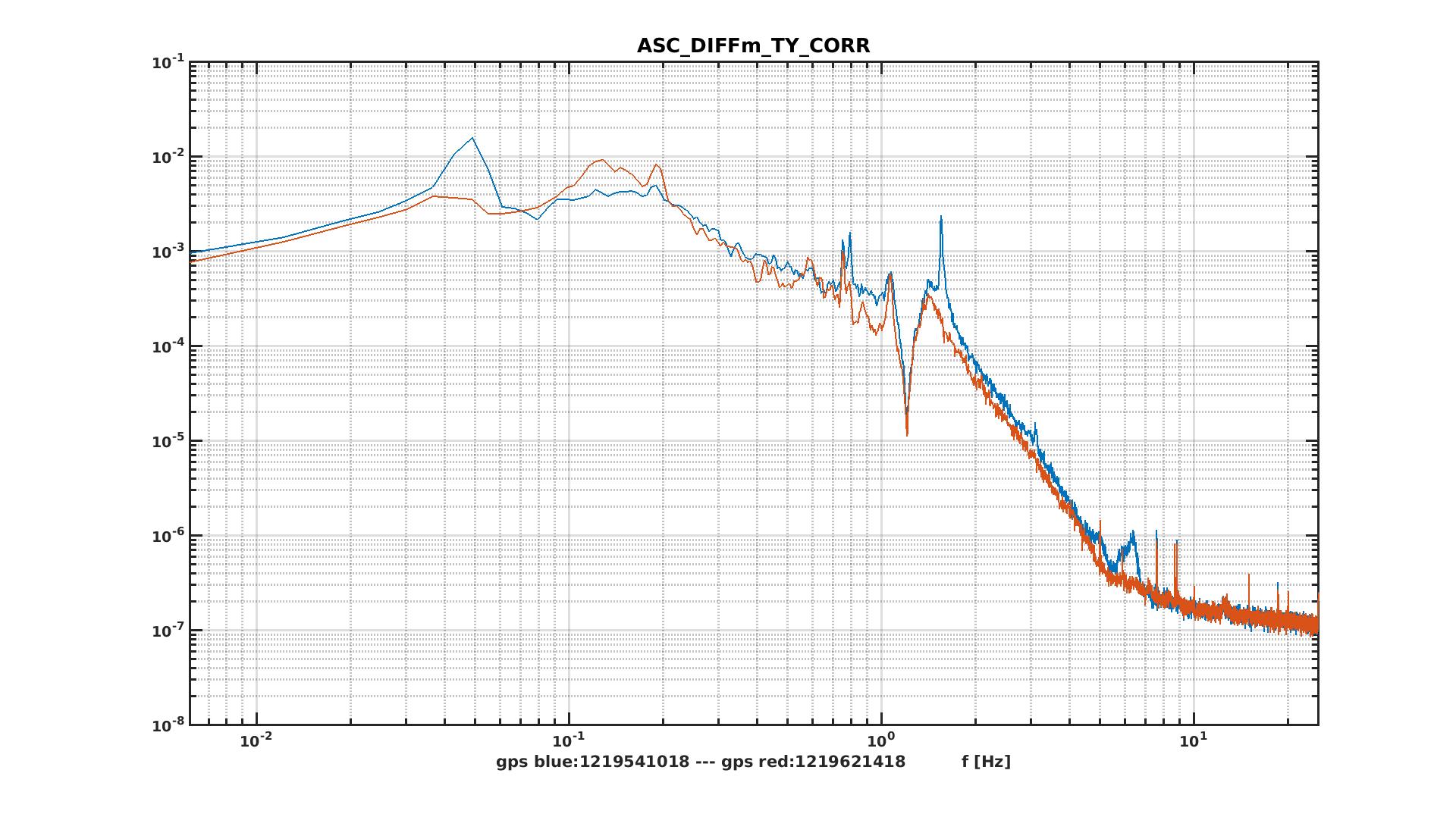
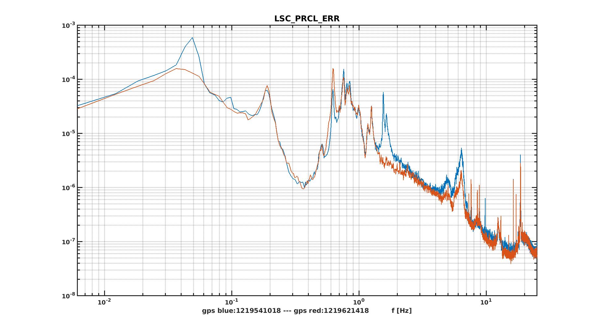
- this allowed to stabilize the dark fringe and reduce a bit some structures in the sensitivity curve;
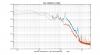
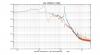
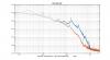
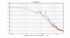
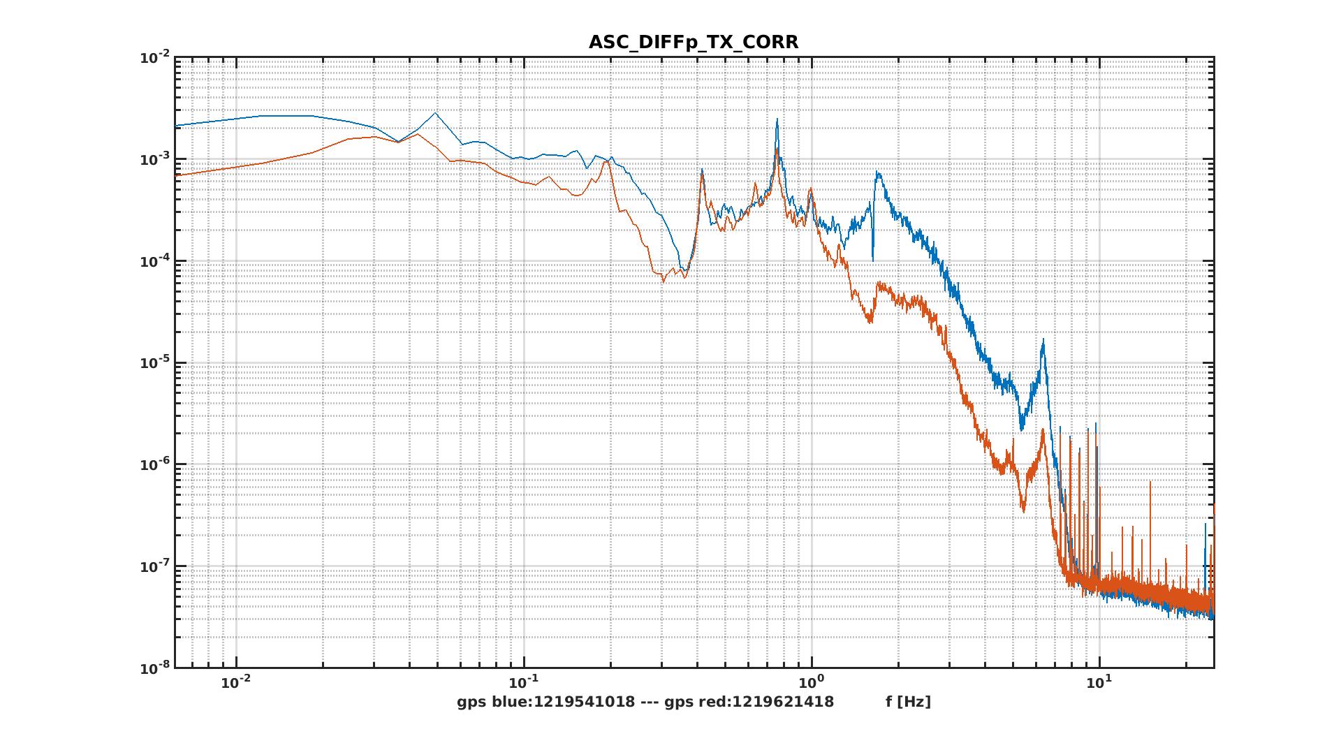
- this also allowed to improve the driving matrix of the DIFFp loop, which helps reducing the 1.5 Hz resonance in the signals (as observed also on SDB1); all of this is now automatically done once in LOW_NOISE_3, 20 seconds after closing the COMMp loop itself;
-
we did some tests with the BS loop in full bandwidth:
- we managed to close it with no issues, but manually and after a long time in LOW_NOISE_3;
- the automatic engagement of the loop failed, even if waiting for 5 minutes once in LOW_NOISE_3; the work on such loop will continue on Friday, along with the investigation on a possible different sensor with B4_QD2.
Side note about the OMCs:
- during the shift we had at first some problem locking OMC1 as there was little power on B1s2, and Romain helped us by reducing the threshold;
- then, following the increase of the 56 MHz modulation amplitude we retuned the DARM offset while we are on RF signal, as it changed calibration; oddly enough, the problem showed up only this morning and not in the past days;
- we recovered the usual ~ 1.5 mW on B1s2 when OMC1 locks , but this is not stable over time, and in the following attempts the same level was not reached every time (see for example the locks around 22:10 and 22:27 UTC); I wonder if the change in the galvo configuration may have an impact on this... If needed, we can move it from OMC1 locking sequence to the OMC2 one.
