Preliminary checks of the calibration data from last Friday don't indicate any large changes in actuator gain, so the other possible culprit is optical gain.
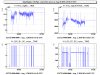
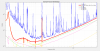
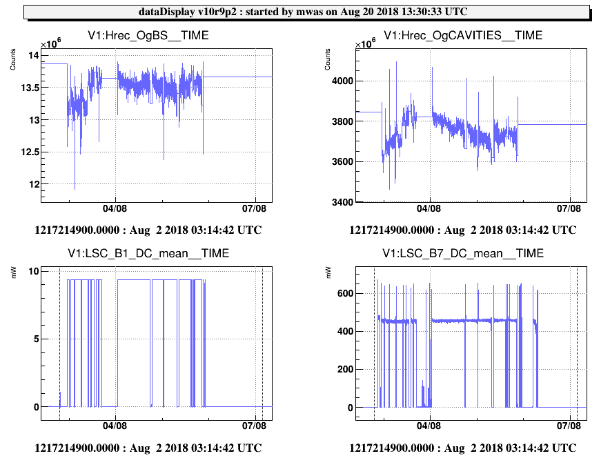
Figure 1 shows the arm cavity gain of two weeks ago ~3.7e9 (W/m?)
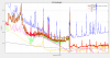
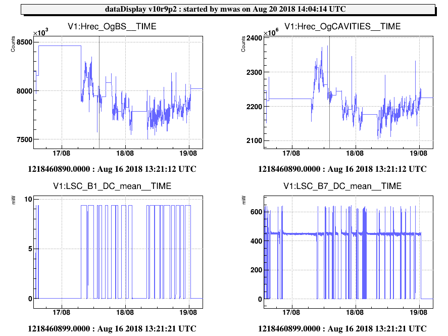
Figure 2 shows the arm cavity gain of last weekend ~2.2e9 (W/m?)
A ratio of 1.7 in the optical gains
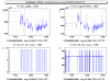
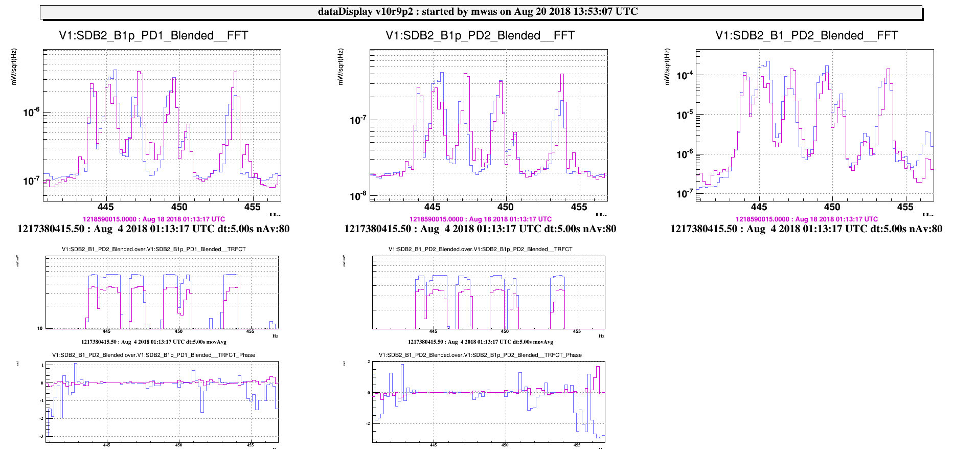
Figure 3: Even more directly we can look at the transfer function between B1p and B1 at the violin modes (which are loud enough to be visible in B1p DC).
For example B1_PD2/B1p_PD1 used to be 530 and is now 360, a ratio of 1.5. Which would point to a drop in optical gain in the path after the B1/B1p beam splitter, so either the OMCs or the B1 PDs.
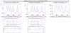
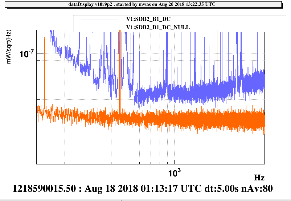
Figure 4: Shows the sum and difference of the two B1 photodiodes, the difference looks like shot noise and is well below the sum. So one of the PDs dying or misbehaving cannot be the explanation for the loss in optical gain.
Assuming the actuator gains are as designed, to match the measured optical gain and power on the B1 photodiode, the losses on the detection bench need to be increased from 35% to 80% in the noise budget model. This make sense, as at a given power on the B1 photodiode, the optical gain is proportional to 1/sqrt(losses), so a factor 1.5 change in optical gain corresponds to 0.35*1.5^2 = 0.8 losses.
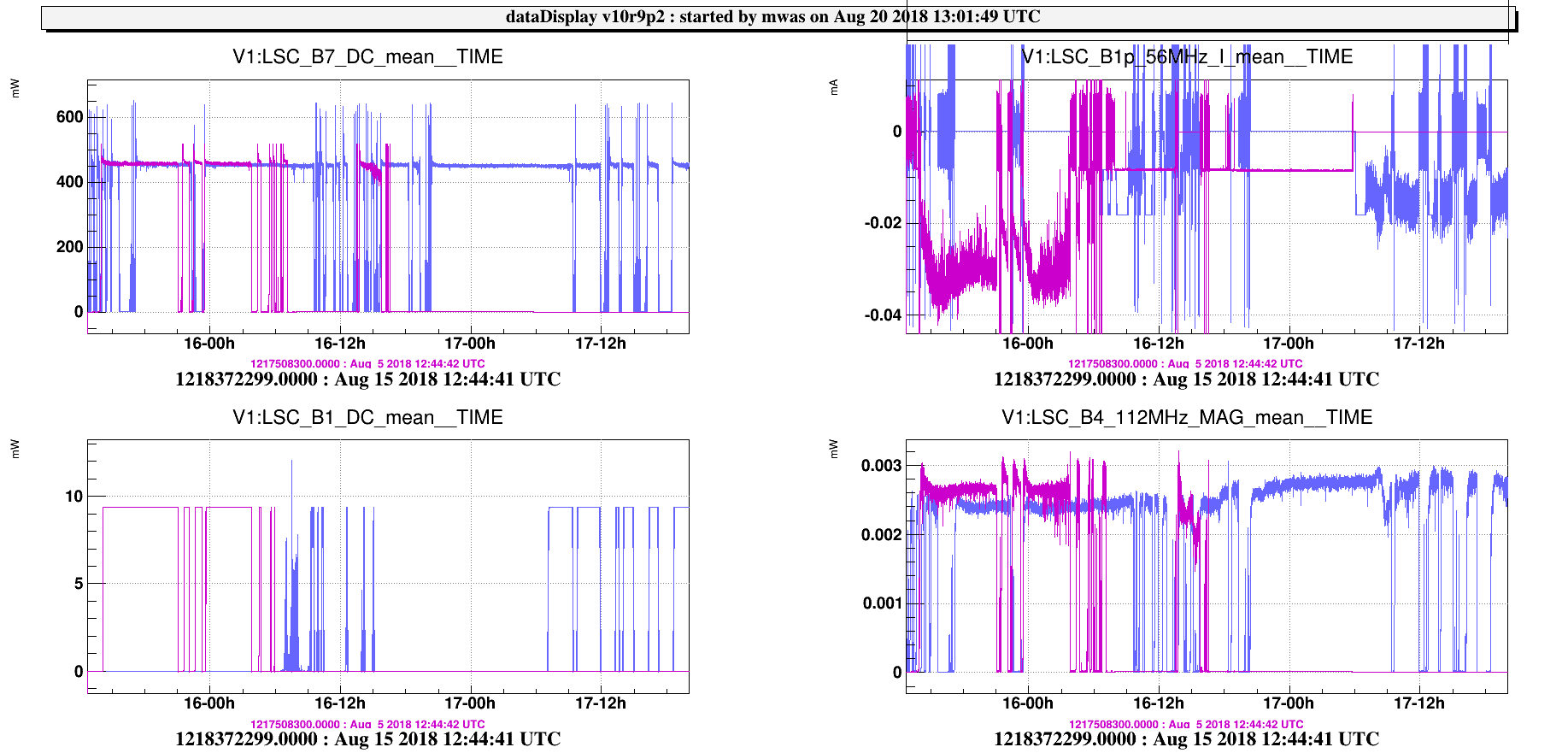
A possible explanation is that aligning OMC1 on the dark fringe beam was a very bad idea. As the dark fringe beam is dominated by higher order modes, this might have actually strongly misaligned the OMC. This could explain a ~30% throughput of the OMC and the extra loss. However, if the OMCs are very losses the same power on the B1 photodiodes should correspond to factor 1.5 larger dark fringe offset measured on B1p_56MHz_I.
Figure 5 shows that the dark fringe offset measured on B1p_56MHz_I has instead *decreased* by a factor 2 from -0.03 to -0.015. So it is not clear if this is really the cause.
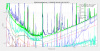
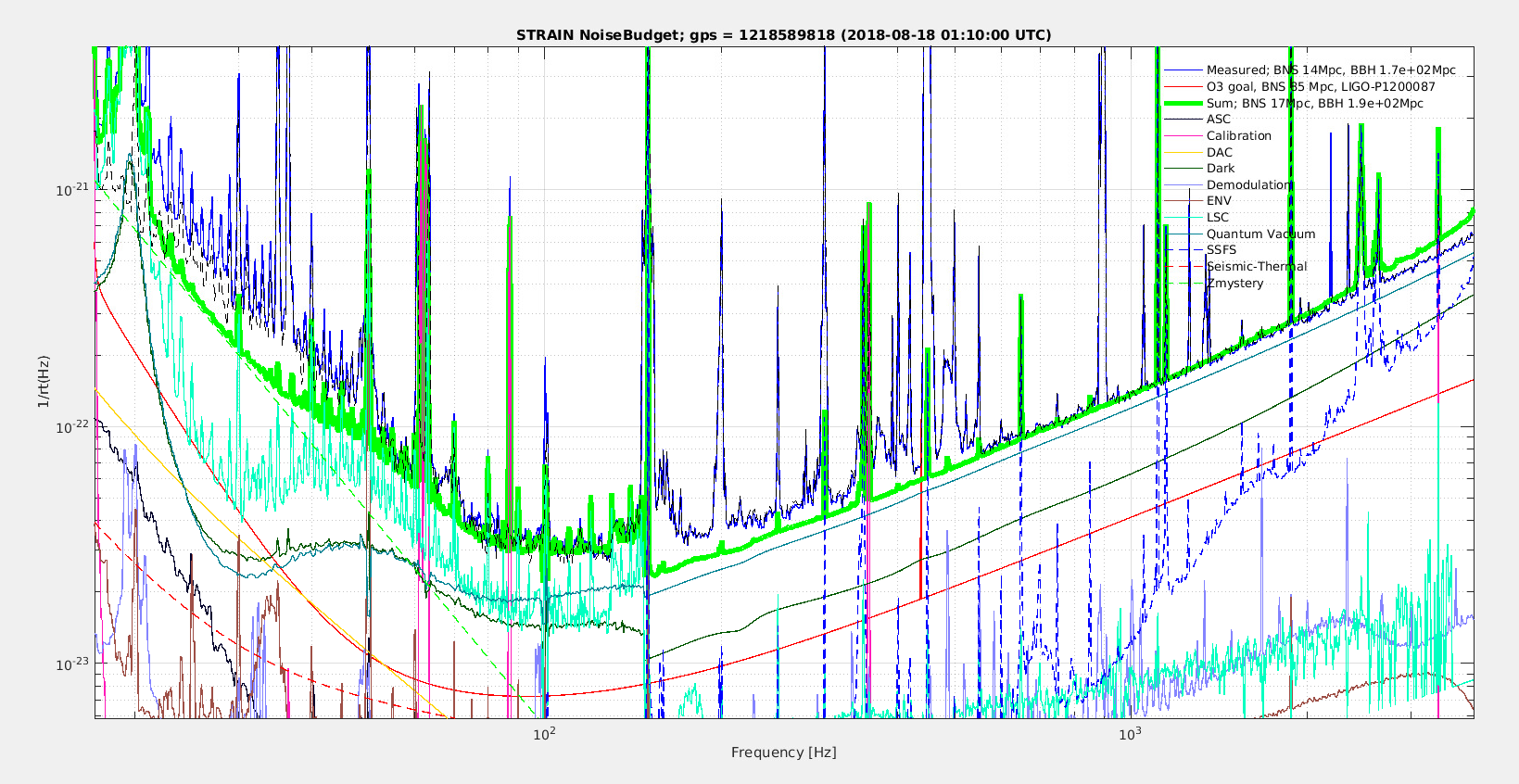
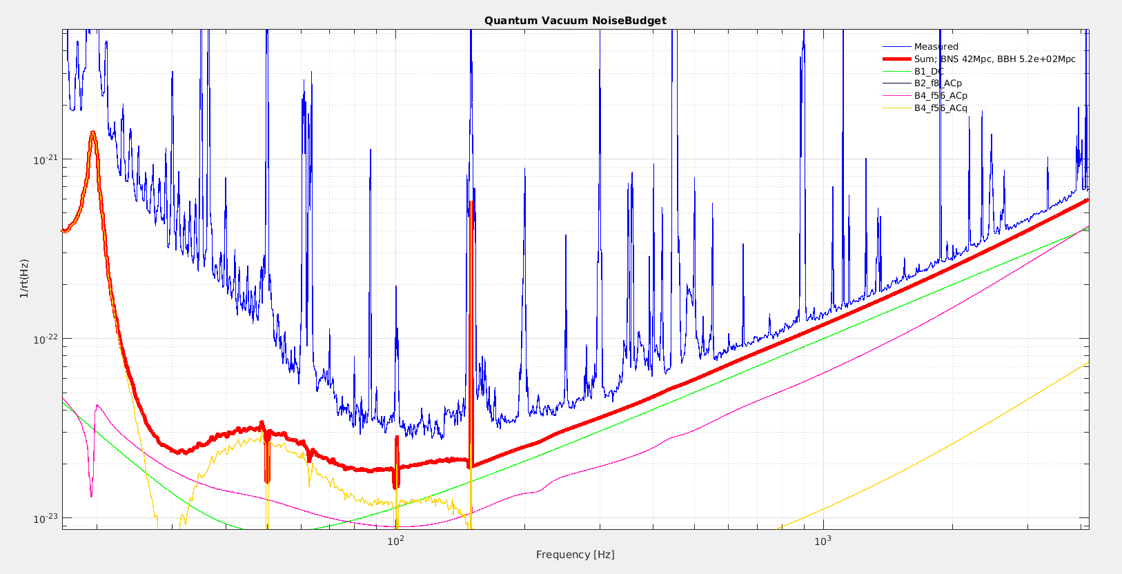
Assuming these additional losses are true. Figure 6 shows a noise budget just after the lock when the range is ~15Mpc. At high frequency it is dominated by B1 shot noise (figure 7), with some contribution of B4 (SSFS) shot noise and electronic noise. At mid frequencies MICH has a significant contribution (figure 8), especially due to the 1Hz comb added through the 56MHz LNFS. Below 50Hz the MICH projection drops but the comb in DARM keeps going up, it is likely that the MICH subtraction is not as good as 2 weeks ago just after the tuning, due to the change in 56MHz optical gain from the TCS. The mystery 1/f^3 noise is probably still present just below the 1Hz comb.

