Since the ITF is getting beack to its operating point, we restarted a characterization of its working conditions.
As a reference, we took the period when the sensitivity was at its best value (31Mpc), GPS = 1190239070 onward.
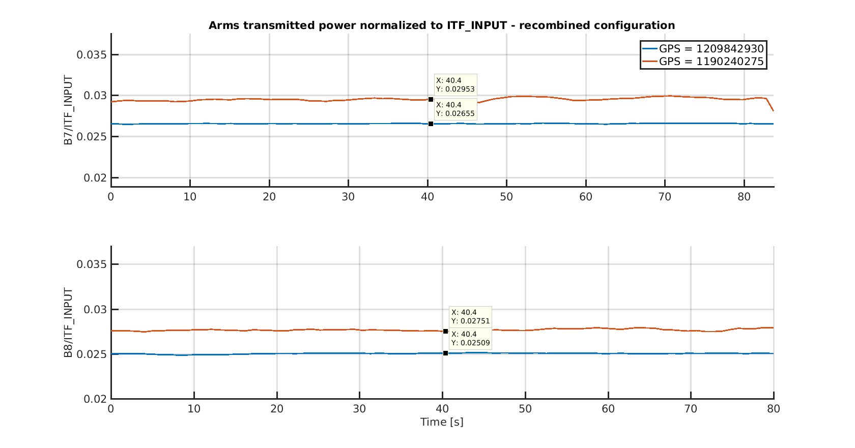
First, we looked at the power at the different ITF ports, and we normalized them to the input power, given by the channel INJ_ITF_INPUT.
Recombined - figure 1
Power transmitted by the arms in recombined results to be lower than before by about 9% for the West and about 10% for the North.
A fast look to the FSR peaks - swinging mirrors just before a lock acquisition - gave us a very rough idea of the total mismatch between the input beam and the cavity mode: from second order mode peak we estimate some 4% of mode mismatch. Moreover, some residual misalignment present in both arms gives an additional 2% of power not coupled in the TEM00. Using these numbers to settle a Finesse simulation, a power drop of about 4.5% is expected.
Another effect to possibily take into account is the etalon. However, even accounting for the maximum possible variation induced by etalon, this would be of the order of 1.2% for the North arm and 2.6% for the West arm (#39767). So it seems that we cannot fully explain the power drop, and a more accurate characterization is needed.
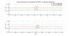
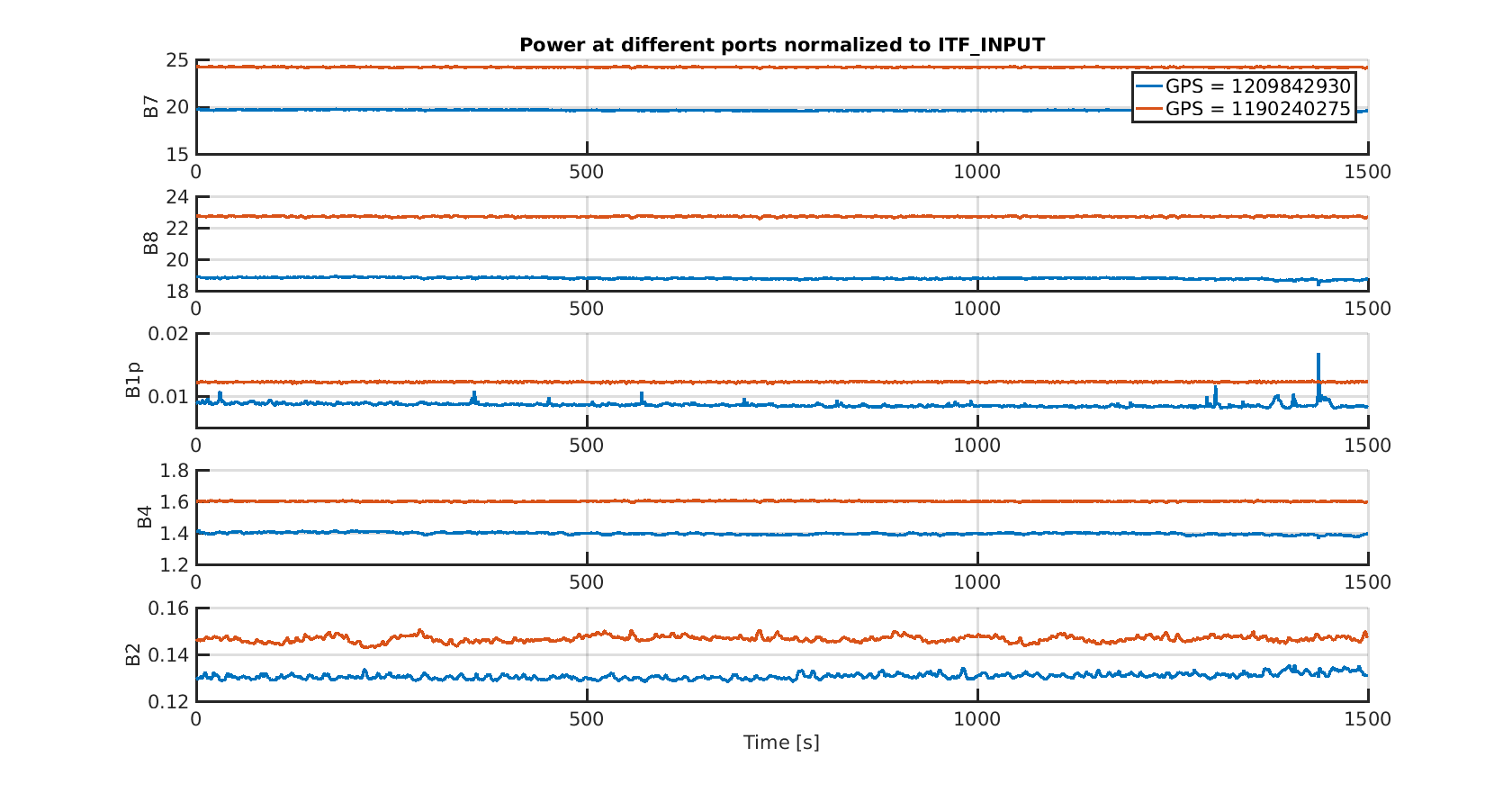
DF lock - figure 2
The second figure shows the power at all the ports when we are in LN3. The power drop for the different PDs amounts to:
| Photodiode | Power drop |
| B7 | -19% |
| B8 | -17% |
| B1p | -25% |
| B4 | -13% |
| B2 | -12% |
Notice that the DARM offset is the same. Moreover, the power of B2 photodiode has been multiplied by 2 to take into account the modifcation which were done on the bench.
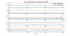
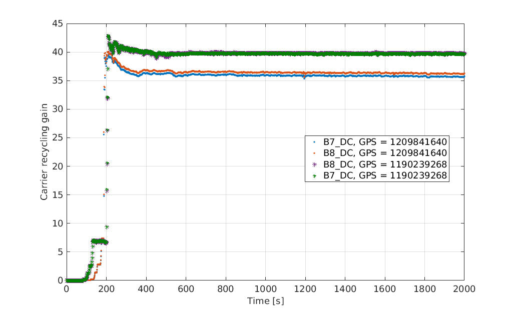
Figure 3 shows the carrier recycling gain as seen by B7 and B8 photodiodes, which is lower by 8%.From this value of the gain we can make an estimation of the maximum losses per arm that could explain the arm reflectivity as seen from the recycling cavity, which result to be around 82ppm (upper limit), against the 72ppm that we derive with the gain of 40 which we used to have.
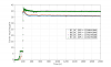
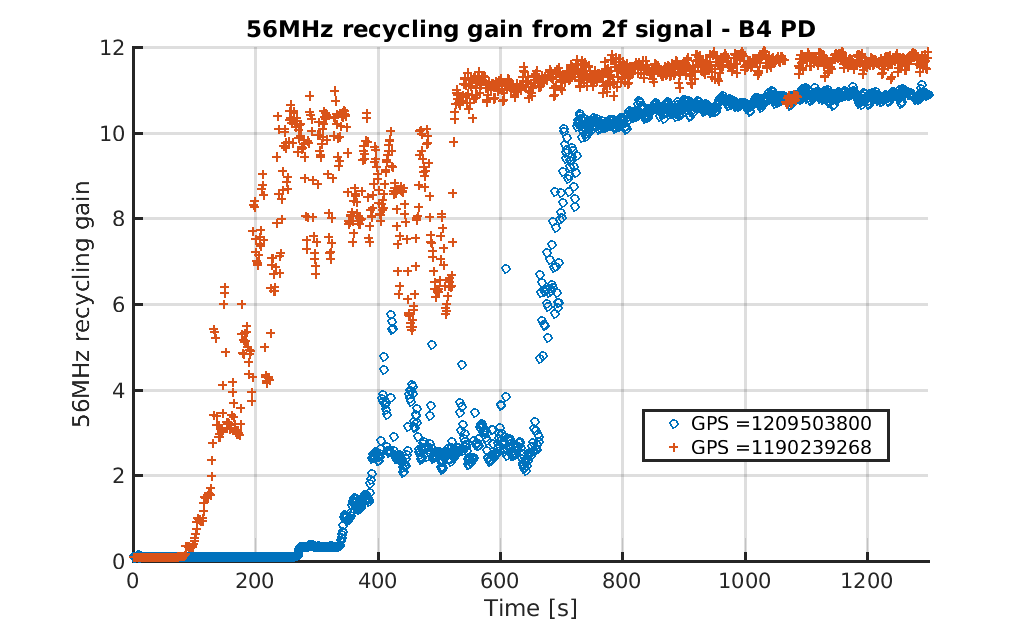
Finally, in figure 4 the 56MHz sideband recycling gain is shown, which is about 16% less than before.
A more accurate characterization campaign is needed to assess the current optical parameters of the ITF.
