The last tuning was done in October 2016. It was done in uncontrolled condition with SDB1 suspended, that involved getting out of the tower and switching off the air flow each time to check the result. But with luck that tuning was quite tuning.
On Feb 15 we proceeded in a more controlled way and with the air flow kept on so better for keeping everything clean. SDB1 was put on it legs, and its position was adjusted by hand to be roughly the same as when suspended. The drawback is that the legs are not in they holes, so the bench can still move if one is not careful enough. The fine tuning of the beam alignment was done by moving the beam splitter to direct the beam onto SDB1. On SDB2 a folding mirror was replaced by an 8% reflectivity mirror, and the 50/50 beam splitter between B1_PD1 and B1_PD2 was replaced by a polarizing mirror, with the p-polarization in transmission on B1 PD1. Unfortunately the change of mirrors on SDB2 was done without a beam, and SDB2 was put back immediately in vacuum on Feb 14, so the alignment could not be checked.
We reimplemented the OMC1 lock in transmission, which allowed us to have a fully independent between on OMC1 (on B1s1) and OMC2 (on B1). In this condition we could lock OMC1 and adjusted the birefrigence of OMC2, and keep the OMC2 temperature close to resonance to check the result. Or alternatively lock OMC2 on B1, and keep OMC1 close to resonance (OMC2 can be locked even if OMC1 is not fully on resonance). Adjusting the torque on the PZT screw of the unlocked OMC causes a few mK temperature transient, but in a matter of minutes the result of the change in torque can be checked.
We have quiet a bit of time trying to find the beam on the B1 PDs, and the power budget didn't match at the end as we were expecting to have 20mW on B1_PD2 and we only achieved 5mW. So it is unclear what is happening on SDB2, and we can't use the B1 photodiodes absolute power levels. Another issue was that we expected only the OMC1 screw to be untightened, but after lots of unsuccesful trials, we realized that the OMC2 screw was completely loose. At the end we achieved a tuning that is a factor 2 worse that was achieved at LAPP or in the tower in October 2016.
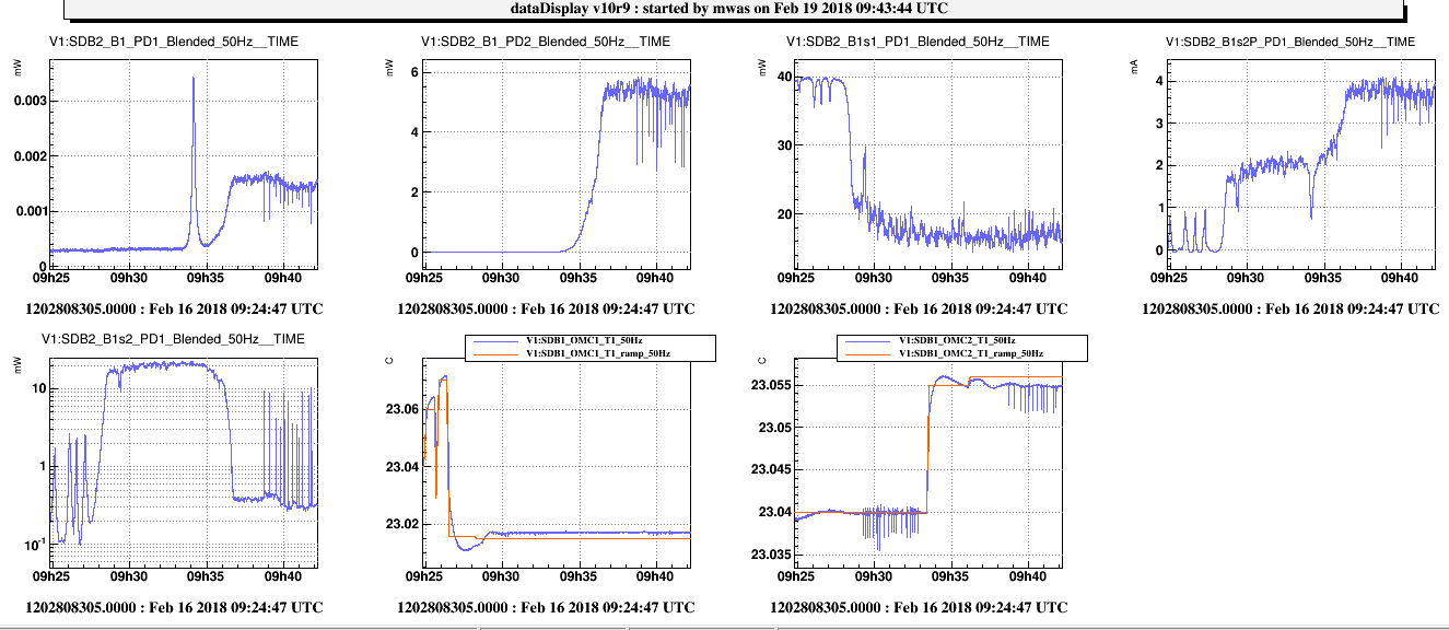
Figure 1, shows a lock of OMC1 at 9h30, with 22mW on B1s2_PD1 after some alignment, then at 9h34 we can see on B1 PD1 the OMC2 going through the p-polarization resonance and then at 9h37 locking on the s-polarization resonance. When the OMC2 locks the amount of p-polarized rejected by OMC2 onto B1s2P PD1 doubles, which means the OMC1 and OMC2 main polarization axis have both p-polarization components but in opposite direction. After some alignment of OMC2 there is 0.37mW on B1s2 PD1 when OMC2 is locked.
In total there is 3.7mW of p-polarization on B1s2P, 0.37mW of s-polarization on B1s2 PD1, which correspond to 4.6mW on the beam as there is an 8% mirror in front of it. This should be compared to 21mW on B1s2 PD1 when OMC2 is unlocked, so 263mW going through OMC1. So there is 3.2% of the light rejected between the two OMCs when they are both locked, with half the light in s-polarization and half in p-polarization. Redoing the computation from Oct 2016 we had 2.4% of light rejected at that time, but only 0.6% was in p-polarization, so there was a good chance that some of the s-polarization rejected light was due to imperfect OMC2 mode matching and alignment that could be further improved.
The temporary polarizing mirror and 8% mirror were left on SDB2, they will be removed during the B1p quadrant reshuffle scheduled in a few weeks.