Figured out that B1_PD2 was still poorly aligned. While aligning it hit the 40mW threshold at which it switches of.
So we added the 50/50 BS on the B1 path, roughly in the spot where B1 crosses the hartman beam at 90 degree angle. Will remove that BS tomorrow.
The BS affects both the s-pol and p-pol beam, hopefully the coating reflectivity is the same for both polarizations?
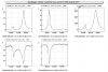
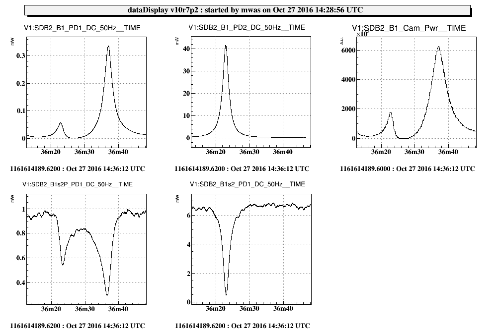
Figure 1. Result with 41mW on s-pol and 0.35mW in p-pol peak, so 0.8% of light in the wrong polarization resonance. I am not quite sure that the BS is very reflective to p-polarization, the p-pol peak was already at 0.3mW with the BS, so it could be that only 0.4% of light is in the wrong polarization.
Note on B1s2_PD1 that the amount of light lost between the OMCs goes down from 6.5mW to 0.5mW, so the total mismatch is currently 8%, and alignment and mode match can be improved.
Improved the locking (now the OMC1 loop is sensible, slightly high UGF at ~5Hz, haven't checked OMC2 in details, but behaves reasonably).
Reduced the modulation depth of OMC2, it was a significant fraction of the losses between OMC1 and OMC2.
Improved the alignment (confusing, because the camera sees mostly the p-polarized light, and the OMC1 lock doesn't like big steps of the OMC2 translation stage).
The result is 0.12mW on B1s2_PD1 when OMC2 is locked and 6.5mW when unlocked so about 2% mismatch between cavities.
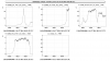
Figure 2. Picture of light lost between the two OMCs.
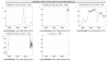
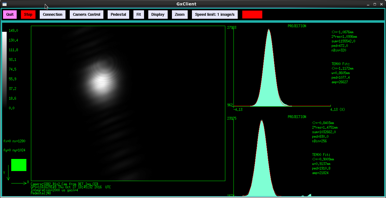
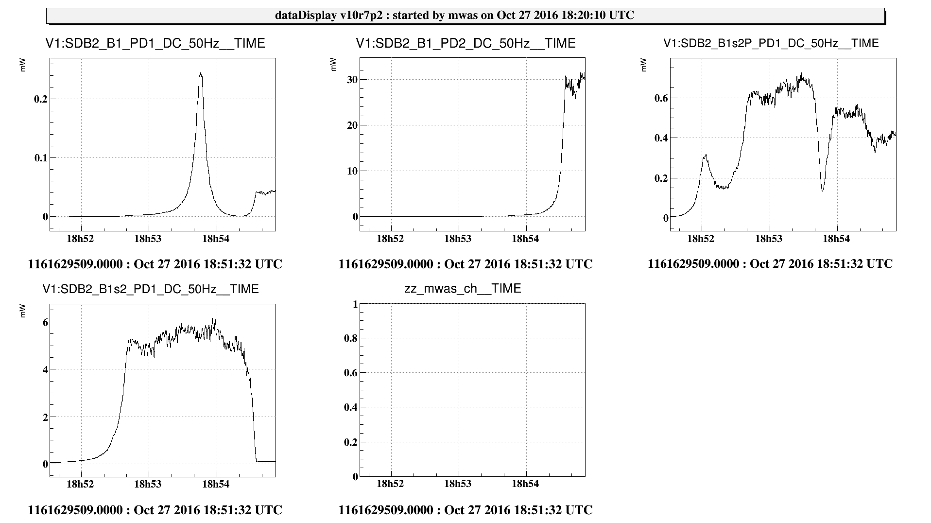
Figure 3. A nice picture of OMC1 and OMC2 locking in a couple of minutes (after an RFC unlock and lock), the two are ramping at the same time to make it faster, and we leverage that OMC2 has its resonance 20mK above OMC1. First the light on B1s2 goes up to 5.5-6mW, then OMC2 locks and it drops to 0.09-0.1mW (figure 4) so about 1.7% is still rejected after OMC2 is locked. Actually, the total is 0.1mW (B1s2) + 0.4mW/12.5 (B1s2P) = 0.13mW, so 2.2% of the total.
The 6MHz has a modulation depth of m=0.22, so there should be m^2/2 = 2.4% of the incoming light power in the 6MHz sideband. Nominally each OMC transmits 0.22 of the side band power. So after the first OMC still 0.22*2.4e-2 = 0.5% of the power is the 6MHz side band, some of it goes through OMC2, and the rest is reflected which amounts to 0.4%.
Hence out of the 2.2%, 0.4% should be the 6MHz being rejected by OMC2, and 1.8% should be the actual mismatch between OMC1 and OMC2, which is similar to the 1.4% that was achieved 2 years ago in Annecy (see VIR-0562A-14). Probably more time spend on birefrigence tuning could improve make us reach this 1.4%, but is not worth at the time, and it is more important to check whether this stays true once the OMCs are in vacuum.
This is just mismatch losses, to which we need to add 2% or 3% of diffraction losses.
