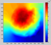
The NI RH has been turned on to verify the TM center in the HWS-DET maps.
RH ON-> 09.07 UTC
RH OFF-> 10.30 UTC

It was not possible to use the first half an hour of the HWS data because of the saturation of the HWS CCD.
Thus, I.N. and G.P. made a quick intervention on EDB to reduce the SLED power by acting on one of the half waveplates.
The data acquired during the last part of the shift allowed to identify the TM center on the HWS maps (see attached plot): this result has been taken as a reference to center the DAS on the NI CP.
Images obtained with phase camera while the NI RH is turned on - Gaussianity of the sidebands and contrast defect seem to improve.
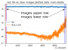
1. figure attached shows the power on B4 and B1p as observed with the main diodes. The time at which the ring heater is turned on is indicated in red. The power leaking to the dark port first slightly decreases and then clearly increases with the NI mirror heating up. The blue lines indicate the gpstimes at which the images shown in the following are taken. Note that the steady state is not reached for the image with ring heater on, first image is taken around the time that the ring heater is turned on.
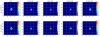
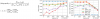
2. figure attached shows the power images on B4. The upper row is the situation with ring heater turned off, the lower once the ring heater is turned on for about 1 hour (as indicated in 1. figure). The images are averaged over 10 s. All sidebands seem to improve in shape, 56 MHz LSB loses power in addition.
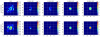
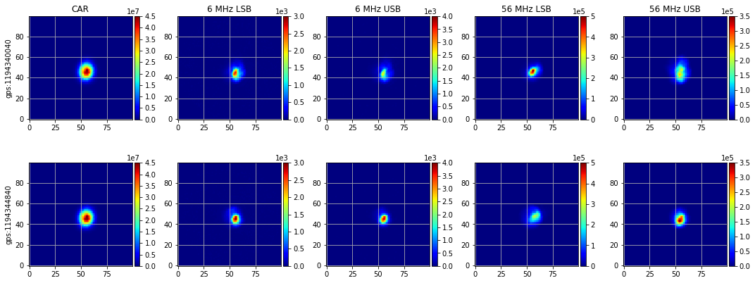
3. figure attached shows the power images on B1p. In contrast to when the WI RH was turned on [40093], with only the NI RH turned on the 08 mode survives in the carrier.
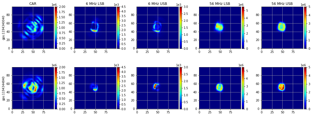
4. figure shows the overlaps. Overlap of carrier with 56 MHz LSB monotonically reduces, while the overlap of the carrier with the 56 MHz and 6 MHz upper sidebands go through a maximum. The 6 MHz LSB overlap is quite stable with only a slight reduction while the overlaps between 6 MHz/56MHz USB and LSB are a mixture of the overlaps with the carrier and corresponding sidebands.
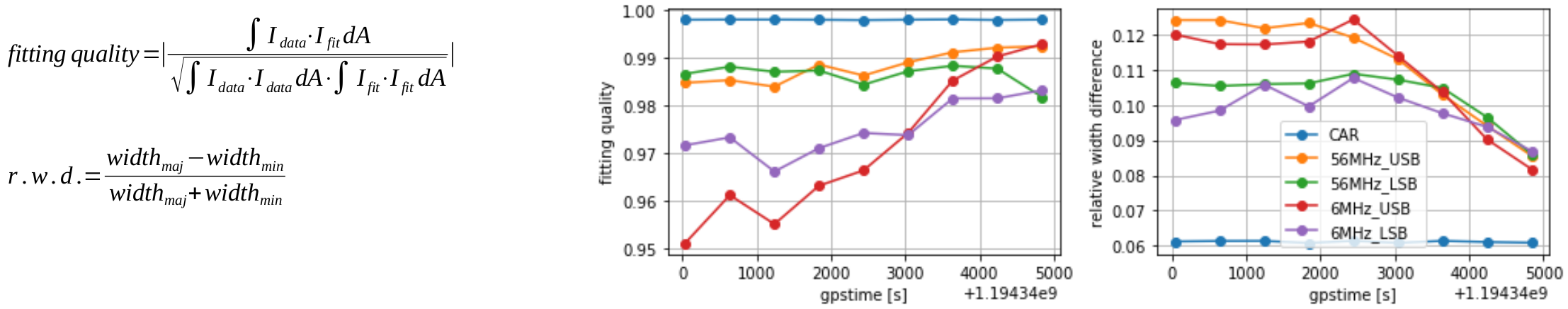
5. The sidebands and the carrier on B4 were fitted with an astigmatic Gaussian. The data is better described by the fit when the NI RH is turned on, i.e. the overlap of fit with data increases (see formula in figure). The astigmatism of the sidebands is reducing as well (again formula in figure, r.w.d. in formula is the relative width difference). Improvements are more pronounced than with the WI RH.
