A preliminary measurement of the CMRF has been performed in order to evaluate the effect of power and frequency noise on the sensitivity.
The CMRF can be broken down to two contributions: one depending on the Finesse asymmetry
CMRF(DeltaF) = (Fn-Fw)/F * 1/(1+(f/f_recy)^2) [1]
and the second depending on the losses asymmetry:
CMRF(DeltaP) = F/2pi * (Pw-Pn) * (f_cav/f_recy) * sqrt(1+(f/f_cav)^2) / sqrt(1+(f/f_recy)^2) [2]
The CMRF is the sum of the two contributions:
CMRF = abs(CMRF(DeltaF) + CMRF(DeltaP)) [3]
Here:
- Fn(Pn) and Fw(Pw) are the Finesse(Losses) of North and West arm, respectively,
- f_recy is the pole of the double cavity, given by: (1-r_PR*r_FP)/(1+r_PR) ~ 1Hz, with r_PR reflectivity of the PR and r_FP reflectivity of the Fabry-Perot cavity
- f_cav is the arm cavity pole (~55 Hz)
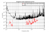
To measure the frequency noise coupling to h, we injected noise on SSFS (#38435) and we measured the TF between SSFS_B4_Err_pre_50kHz and Hrec_hoft_20000Hz. Figure 1.
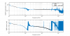
Then,we projected the coupling on Hrec, taking a period of clean data (2017/07/05, 21:15:00 UTC). The result is shown in figure 2, where only the data with a coherence greater than 0.8 have been considered.
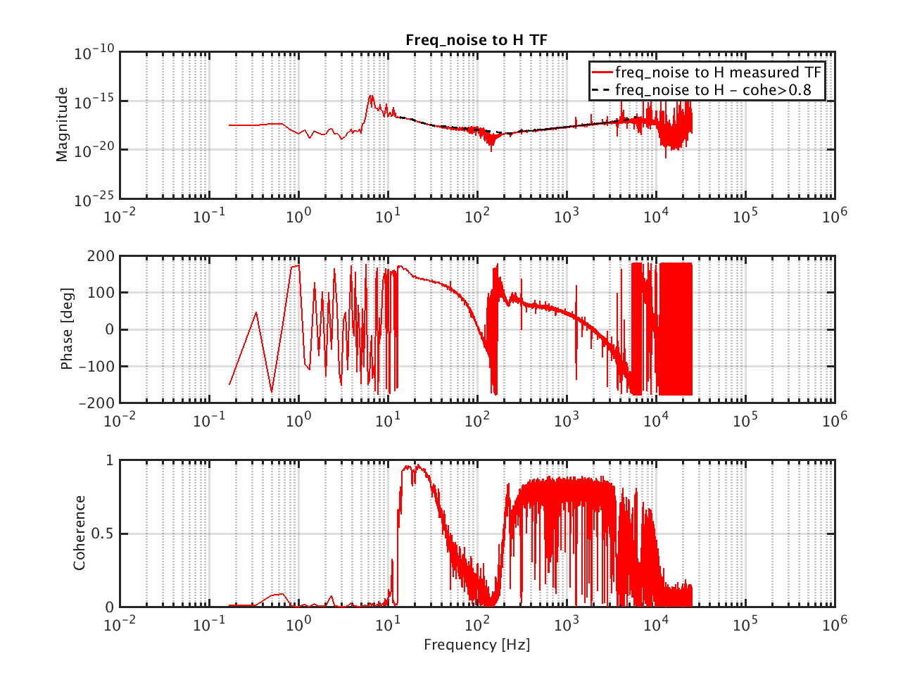
Finally, the CMRF function have been computed. To do this it is necessary that:
- the response of B4 photodiode is taken into account: this is obtained by dividing the SSFS TF by the SSFS control filter
- the error signal is calibrated in Hz/V: this has been done starting from the RFC error signal calibration (VIR-0369A-15) and taking into account the loop gain between IMC and SSFS loops
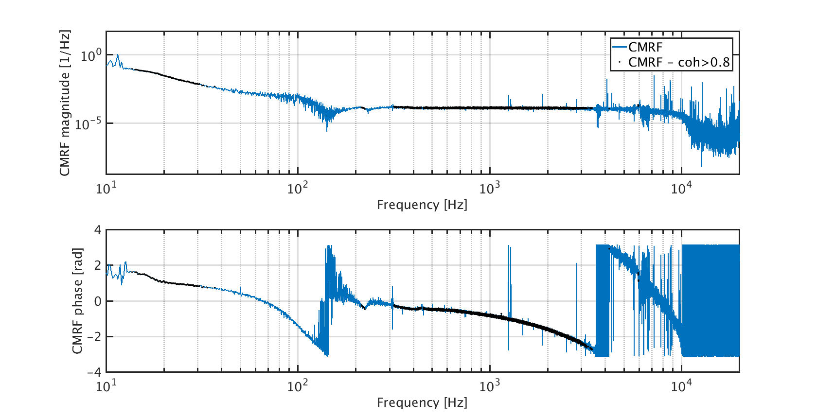
Therefore, we obtain the transfer function shown in figure 3. Also in this case, the black dots corrispond to the part of the measurement with a coherence greater than 0.8. Moreover, it has to be considered that the low frequency part (below 100Hz) is probably not meaningful, since the FmodErr tuning was not optimal and this introduces a coupling of the MICH noise into DARM.
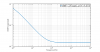
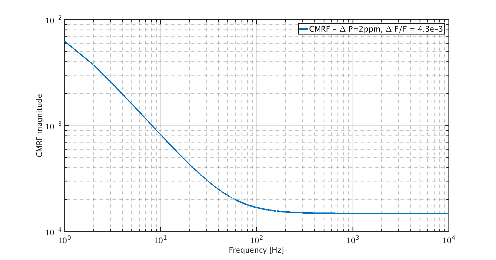
The value at high frequency (200Hz-3.5kHz) of the CMRF can be reproduced by adding a losses asymmetry of 2ppm in the formula [2]. Figure 4 shows a plot of the analytic function [3] with DeltaP= 2ppm and DeltaF = 2.
It must be noticed that, since the double cavity pole (f_recy) is at about 1Hz, the Finesse asymmetry mainly contributes in DC (so mainly at the contrast defect) and at low frequency, while the losses asymmetry contributes in the frequency band >100Hz.
More investigations are needed, first because the measurement has to be repeated for the new sensitivity. Then, a new noise injection giving a higher coherence below 100 Hz is needed in order to better highlight the contribution of the Finesse asymmetry.
