This morning we pursued the investigations of SDB1 scattered light started last week (logbook 38340). The following tests were performed (always with SDB1 beam drift control off, unless otherwise specified):
- We scanned the vertical position of the SDB1 bench from -1.3 mm to +2.1 mm around its nominal set point by acting on the top stage of the suspension. No clear improvement was obtained on the camera images.
- We scanned the vertical position of SR from -1.1 mm to +0.6 mm around its nominal set point by acting on the top stage of the suspension. No clear improvement was obtained on the camera images.
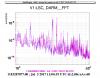
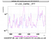
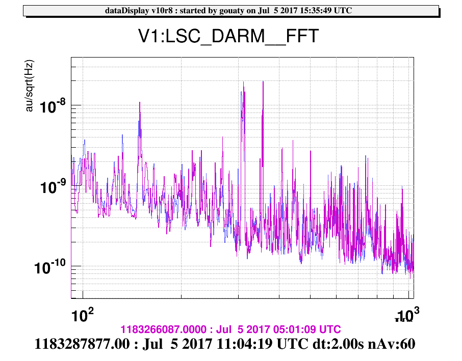
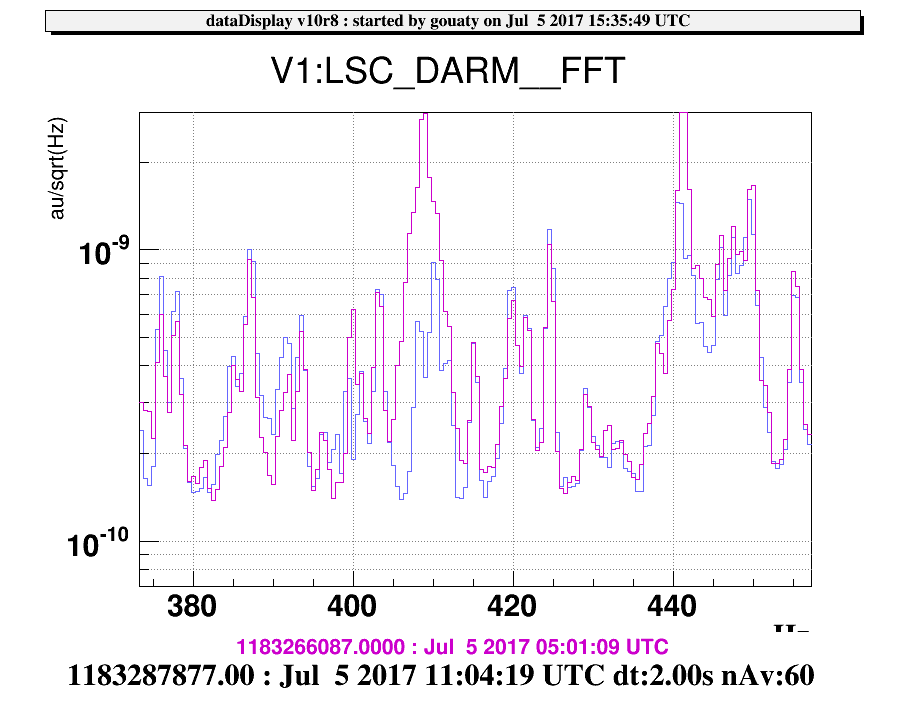
- We found a combination of motions (SR, SDB1 and SDB2 all lowered by ~1 mm) where the alignment was preserved on the OMC and on the photodiodes. At this point we switched back on the beam drift control (but its action was only to adjust by 5 urad the TX position which allowed to keep a good alignment on the OMC), and it was possible to go to low noise 2 with this configuration. The obtained DARM spectrum (blue curve in Fig.1) could then be compared to the one obtained with standard positions (purple curve in Fig.1). A few lines are reduced on the blue spectrum but they are known to depend on the alignment conditions (and B1p_DC fluctuations were smaller at this time) so they are probably not related to our change of configuration. There could be an improvement around 408 Hz, see Fig.2. Overall the benefit of this tested configuration was not obvious at all so we went back to the usual set points.
- We scanned the TX position of the SDB1 bench from -200 urad to +300 urad, without any obvious improvement on the camera images.
- We scanned the TX position of SR (acting on the marionetta set point) from -500 urad to +500 urad, without any obvious change on the camera images.
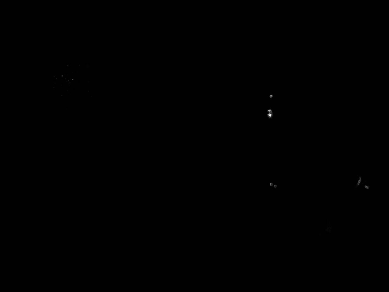
- We scanned the TY position of the SDB1 bench from -4 mrad to +3.5 mrad. This action had a clear impact on the relative position between the B1 and B5 beams as shown in Fig.3 (image with SDB1 TY = -4 mrad) and Fig.4 (image with SDB1 TY = +3.5 mrad). In fact this the B5 beam position which seems to change. On Fig.3 the two beams on M1 are aligned horizontally and thus are only separated vertically, while on Fig.2 B5 is clearly shifted horizontally with respect to B1. It is not clear which conclusion we should drive from this, but moving SDB1 in TY is the only way we have found to be efficient to imply such change on the B1/B5 relative position on the M1 mirror image (or course the actuator range for the TX motion is much more limited).
- We scanned the TY position of SR (acting on the marionetta set point) from -3 mrad to +3 mrad, without any obvious change on the camera images.
Investigations will be pursued tomorrow morning.

