Tonight we implemented the temporary solution of reducing the 6MHz modulation depth after we reach dark fringe, to prevent the B4 PD from saturating. This allowed us to run smoothly with the SSFS and MICH locked on the 56MHz signals, using B4 PD1.
Franco worked out the commands to remotely change the amplitude of the 6MHz in the LNFS, and added these to metatron. The nominal amplitude is 15dBm, this is reduced in steps of ~1dBm over about 10 seconds to -6dBm. In the DOWN state the amplitude is restored so the arms and RFC can relock. (Note, Diego disabled the RFC slow loop, so tonight we've been letting the arms drift freely in CARM.) We found that large steps of the modulation depth - like, from 15dBm to 0dBm - would cause the ITF to unlock.
Paolo changed the drift control of the mirrors so the loop gain was normalized by the line amplitude, this allowed us to reduce the line height enough to lock the OMCs, without losing the alignment control.
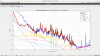
After fixing an issue with the MC F0 z position (after an unlock, a large correction seemed to be offloaded to the MC top stage from the SSFS, see Figure 5), we reached dark fringe and Michal locked the OMCs. There is still a lot of alignment motion which makes the OMCs difficult to lock, the transmitted power can fluctuate by 3x. In order to lock the second OMC, we first handed DARM off to B1s2, this stabilized the power on B1 enough to lock the second OMC.
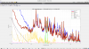
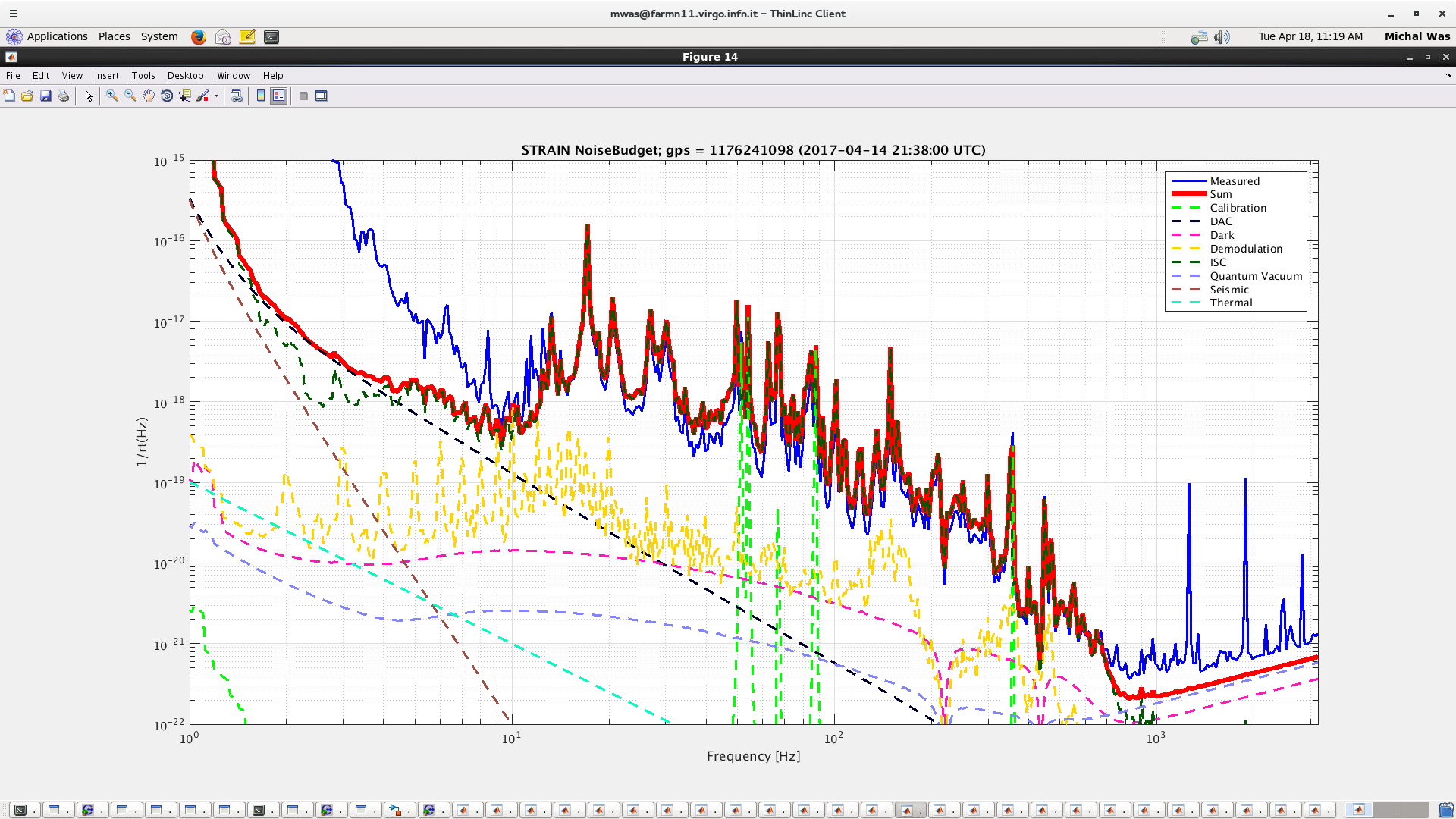
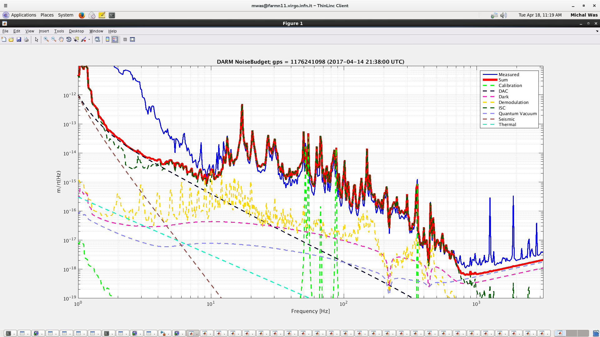
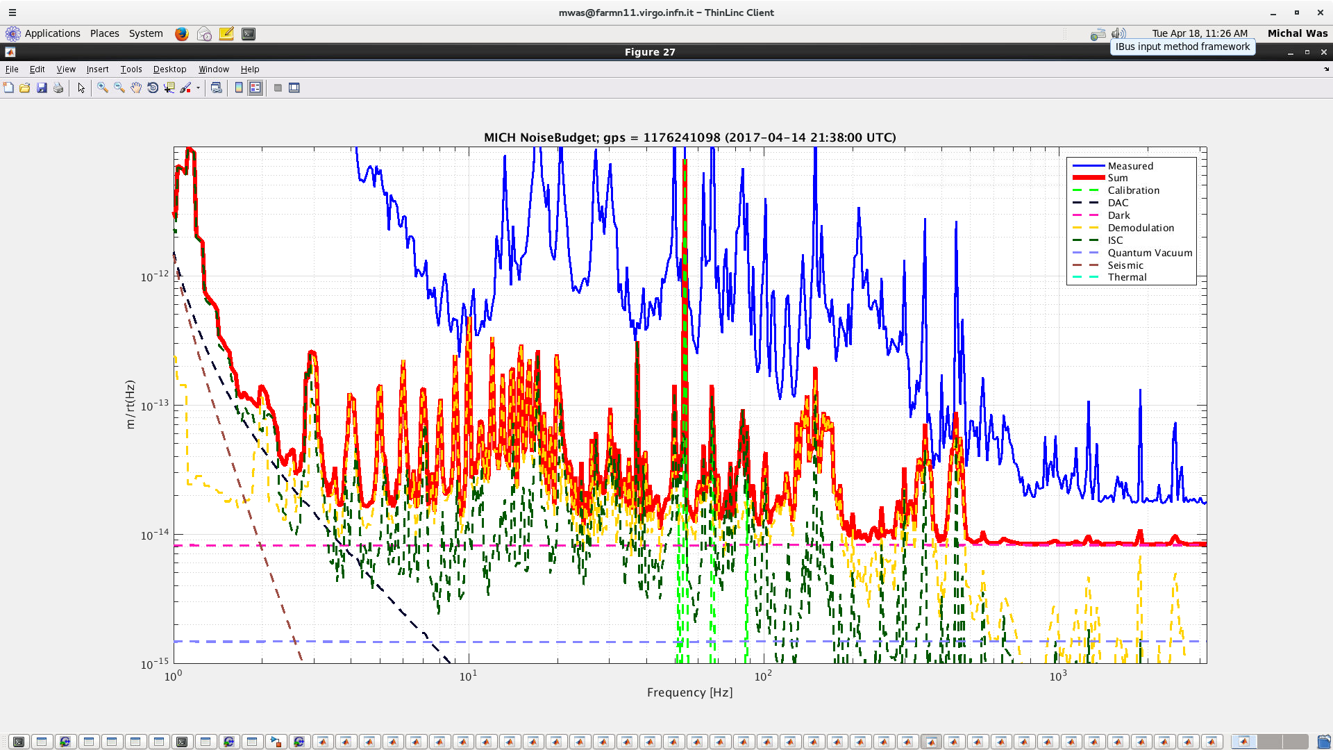
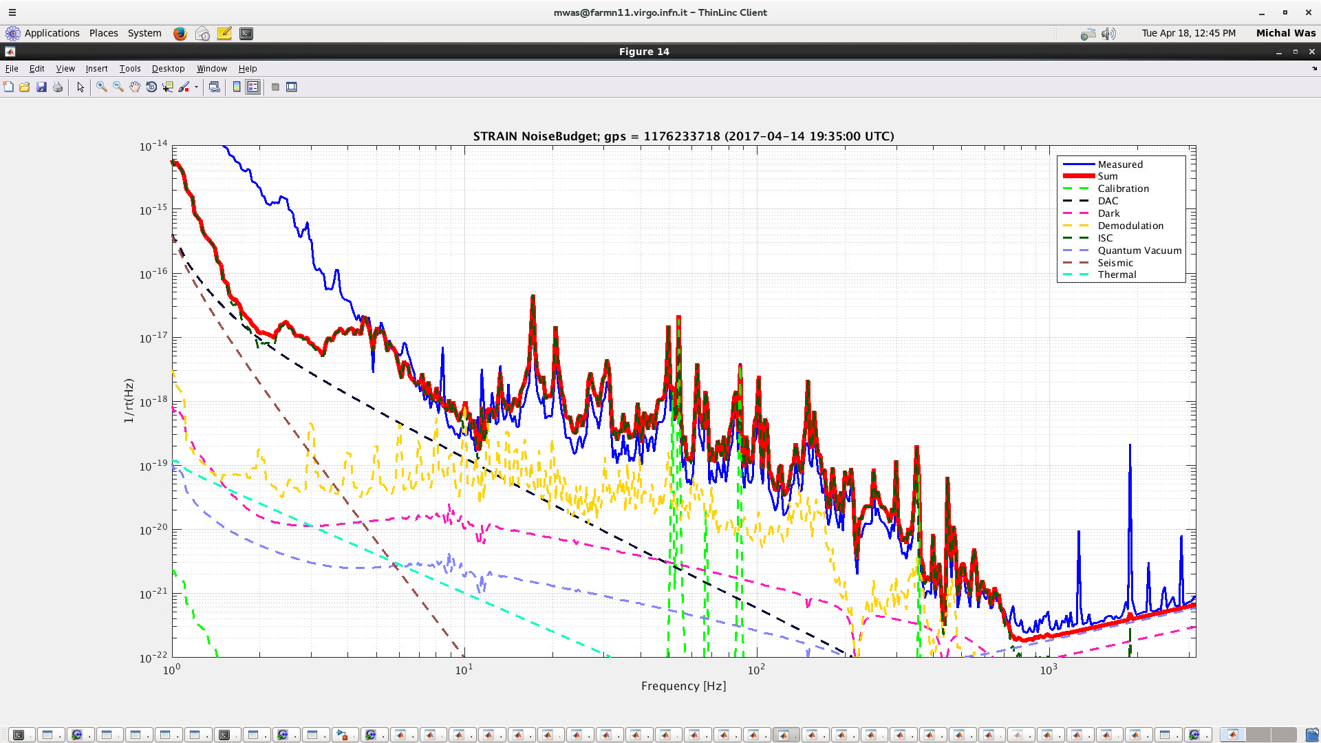
The DARM noise is better (see Figure 3), but still dominated by MICH (see Figure 4). We are not limited by DAC noise yet.
The procedure to hand off DARM to B1s2 is:
- Lock the first OMC. Set LSC.B1_DC_IN1.B1s2_DC = 1.0. This sets up the path to send the OMC transmitted light to DARM. The simple path is in the LSC_Acl config file, lines 116-121; there's a more complicated path with gain scaling that we can use once things are more stable.
- Tune the gain, LSC.B1_DC_GAIN, so that the transfer function between LSC.B1_DC_INPUT and LSC.DARM_INPUT is unity. This is usually about 1/2000. If the gain is tuned well, the offset usually doesn't need to be touched - this can be absorbed into the DARM offset when you make the handoff. The DARM ugf servo is good enough to keep track of the gain.
- Set the DARM input matrix element for B1_DC_INPUT to 1.0, and B1p_56MHz_I to zero. Voila! DC readout.
Our longest lock tonight was almost one hour, during which we handed off to B1s2, and then locked the 2nd OMC and handed off to B1_DC. We found that the light was fluctuating enough that the B1 PD was saturating frequently; the rms is dominated by a line around 16Hz, and then the 50Hz power line. These lines need to be reduced in order to get the full benefit of B1_DC at high frequency.
During a second good lock, from about 21:35 to 22:00, we ran on B1s2 as before, and this time enabled the SSFS, MICH, and PRCL boosts. Also the amplitude of the permanent calibration lines was larger, this should be helpful for calibrators. This lock ended due to the alignment instability in TX that we sometimes observe.
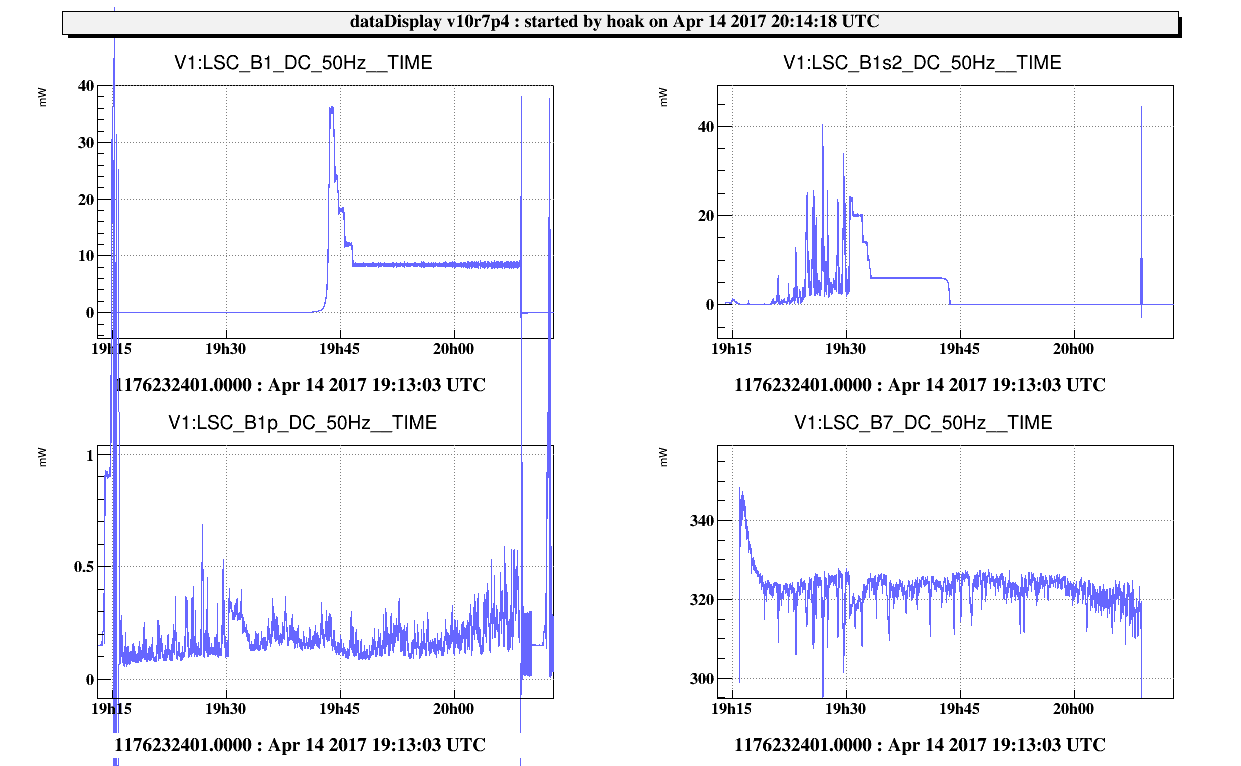
Figures attached are:
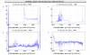
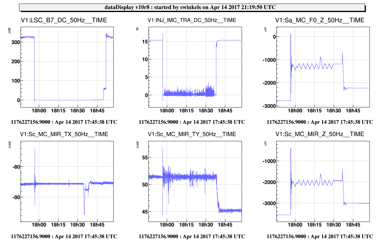
- Timeline of our best lock, we were locked on DC readout using B1s2 from 19:34 UTC to about 19:42, and then on B1_DC from about 19:47 UTC to the end of the lock. In between, we made the handoff from the 1st OMC to the 2nd, and tuned the DARM offset to try to minimize the saturations. The data on B1s2 from this lock is probably the best for coherence analysis.
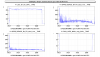
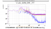
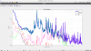
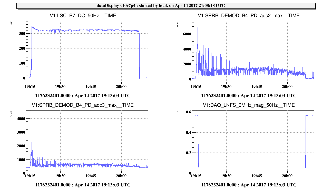
- Illustration of the 6MHz modulation depth reduction during dark fringe. The saturations in the B4 PD go away once the modulation depth is reduced.
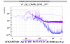
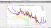
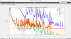
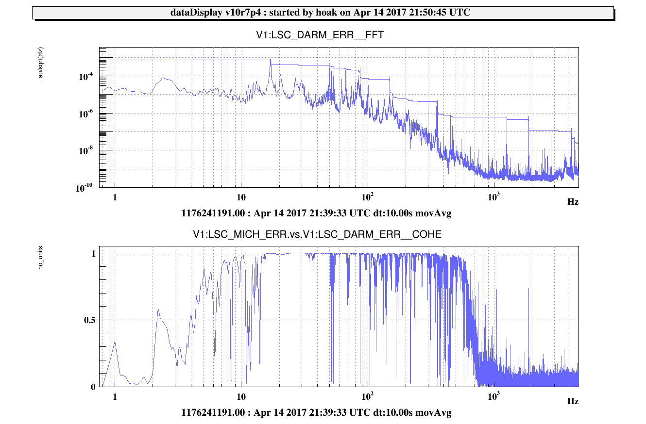
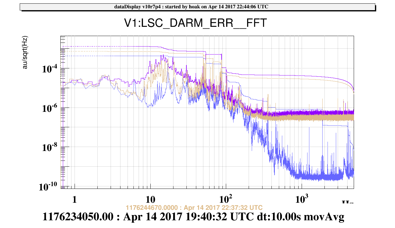
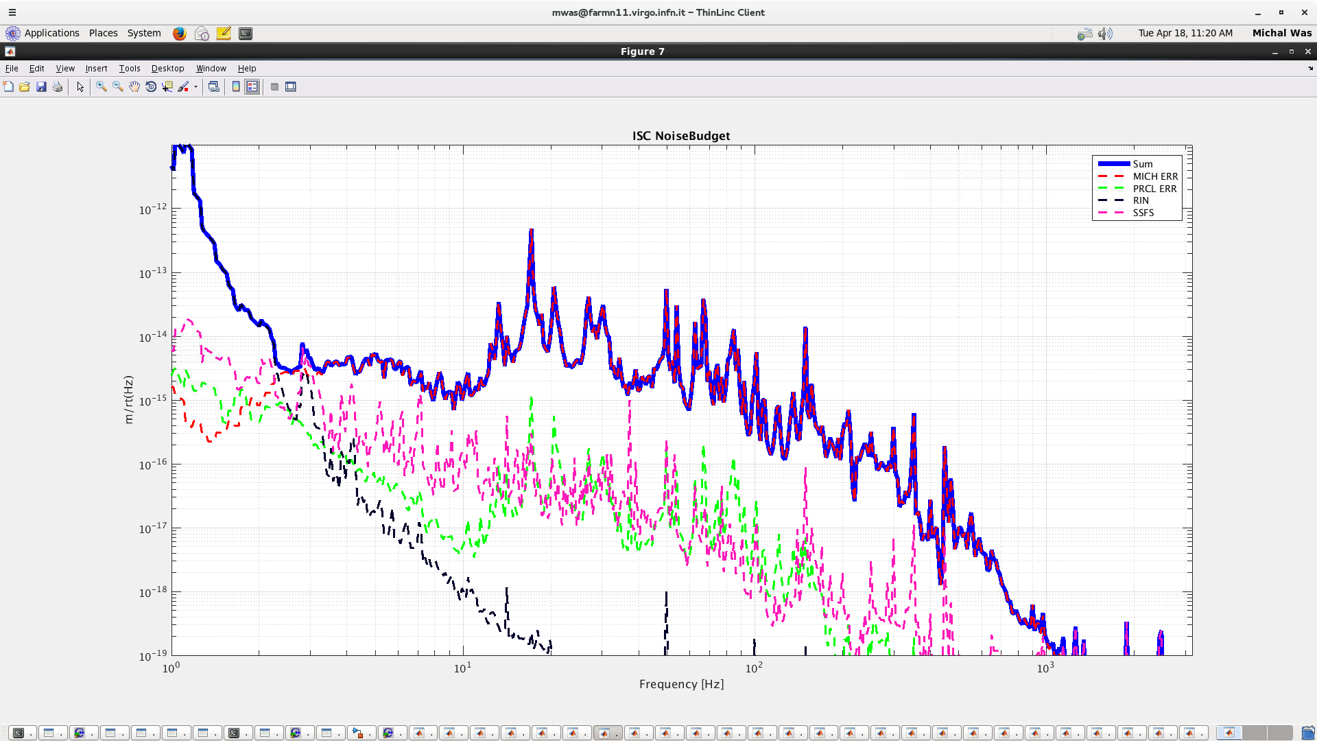
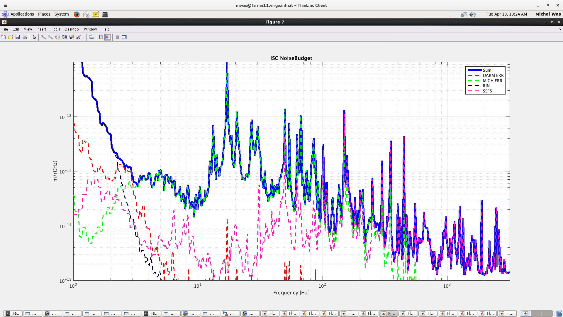
- Plot of DARM_ERR on B1s2, compared to DARM on RF with MICH on the 56MHz and the SSFS on the 6MHz. The reduction in phase noise coupling has helped, and the noise at high frequency is not bad.
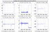
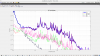
- DARM and MICH coherence during the lock on B1s2.
- A plot of the IMC issue from earlier in the evening. MC_F0_Z got a big kick at the unlock, and the MC mirror started scanning to find (unsuccessfully) lock. Gabriel and Valerio advised us to set the IMC metatron to DOWN and move the MC mirror back to where it started. It looks like the angular position of the mirror was shifted by the automatic alignment after we relocked, not sure if this is significant.
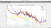
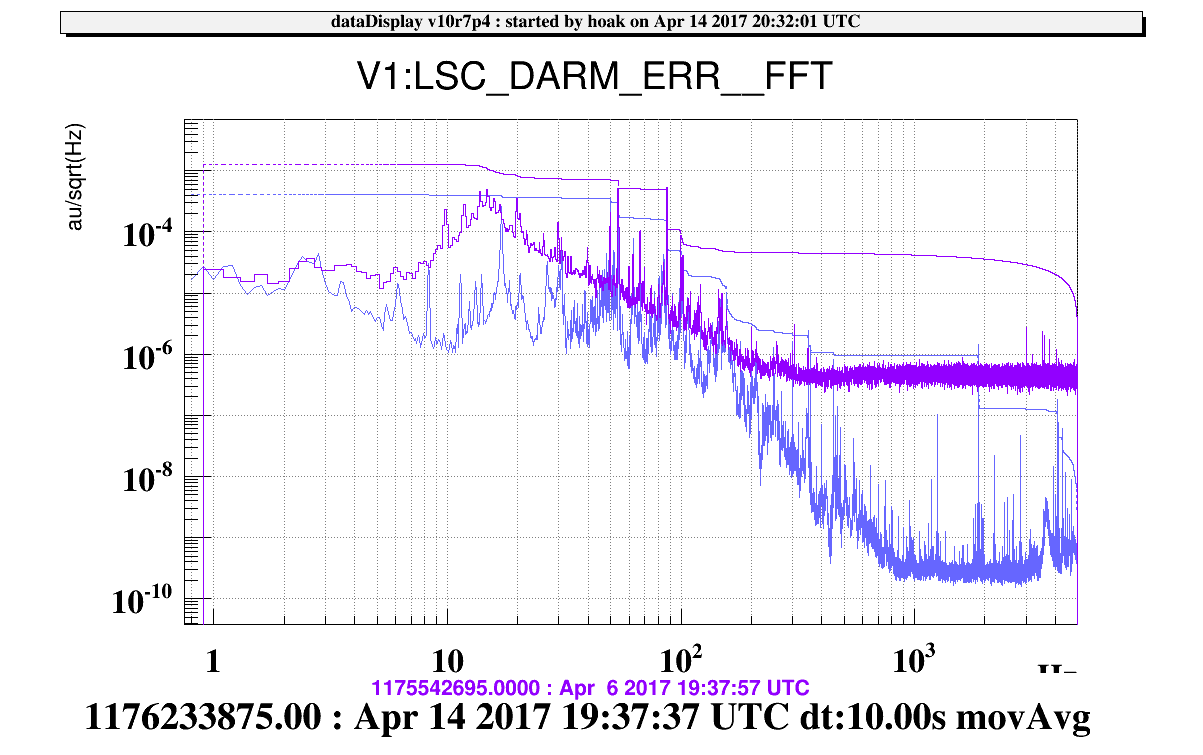
- Comparison of DARM showing improvement from the mitigation of phase noise coupling, and then DC readout. Purple is SSFS on 6MHz, gold is DARM on RFwith SSFS and MICH on 56MHz. Blue is DC readout.
Notes:
- Earlier in the night we noticed the SSFS boost was causing glitches in MICH. We switched to a first-order boost, and the glitches went away. Also there were some communication issues with the SSFS_Ctrl process, these went away after a restart of the process. There's still an issue with the SSFS, we foun the SPRB 56MHz phase and the relative phase were changing thoughout the evening, and the SSFS appeared to make the SPRB_B4_56MHz_I channel noisier when it was engaged.
- In order to lock the OMC, we have been using a DARM offset of 0.005, but at first we used an offset 3x larger in order to get the DC signal above the power fluctuations due to alignment. These could also be due to residual DARM motion, maybe from sideband fluctuations while we're still locked on the RF signal.
