# Master laser
the temperature of the crystal was in an area where mode hops occur. There the ML emits two modes at 2 different freq with 2 diffrent amplitudes. at each unlock of the slave laser, the relock can be done whatever the mode. Once locked it remains the carrier (20 W slave laser) plus the two side bands whose amplitude is set by the MasterLaser amplitude mode. Therefore the PMC sees two different side band level according to the ML_mode and the PMC loop sees its gain changing by a factor in our specific case. This appeared as a PMC flaw but related to a wrong Temp setting upstream.
The noticeable temperatures are:
with T_ML= 22,27 °C, 2 modes are issued
with T_ML= 19,8 °C °C, 2 modes are issued
--> Mean T = 20,9 °C one single mode
# slave laser injection - Lateral bands
- we measure 732 mV pp at the "EO monit" port (on the LB, output of the EO driver of the 14 MHz crystal), loaded with 50 ohm, with a scope
that means Lateral bands amplitude of 732 mV pp * 123 mrad/V = 45 mrad pk (123 mrd /V , see moduleo&.pdf in https://scientists.virgo-gw.eu/ISYS/Documentation/Electronics/Coulon_Nice_Elec/Others/)
we use to have 86 mrad in the past (see Laser bench nominal data.pdf in https://scientists.virgo-gw.eu/ISYS/Documentation/LaserLab/LB/)
the discrepancy might come from the fact that the mod freq has been changed from 13,95 MHz formerly to 14,31 MHz with no tuning of the capacitor associated with the resonant filter below the crystal (cf moduleo1.pdf) when the 14 MHz crystal has been swaped with a DDS
- we had to tune the phase too by adding a 2m long cable ( delta_phase = 51 °)
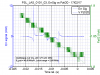
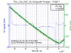
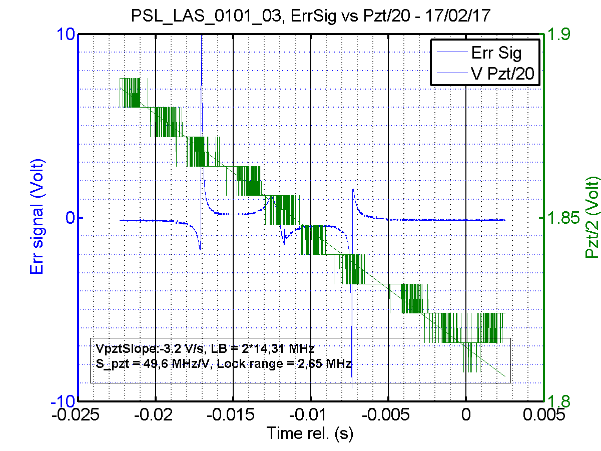
# Slave laser injection locking range
the master laser power before the slave laser (upstream the faraday iso) is 0,397 W, the slave laser outptu power is around 19 W
- the locking range has been measured to be 2,3 - 2,6 MHz see plot 1/2
- the pzt sensitivity is around 45 - 49 MHz/V
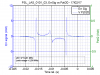
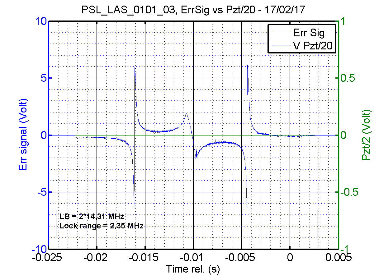
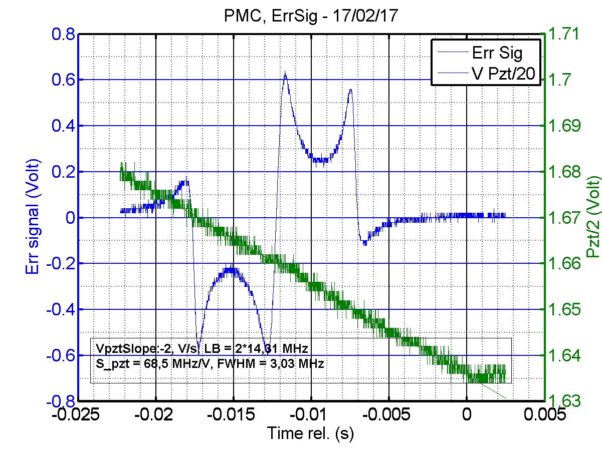
# Slave laser injection error signal
plot 3 gives an insight of the injection error signal
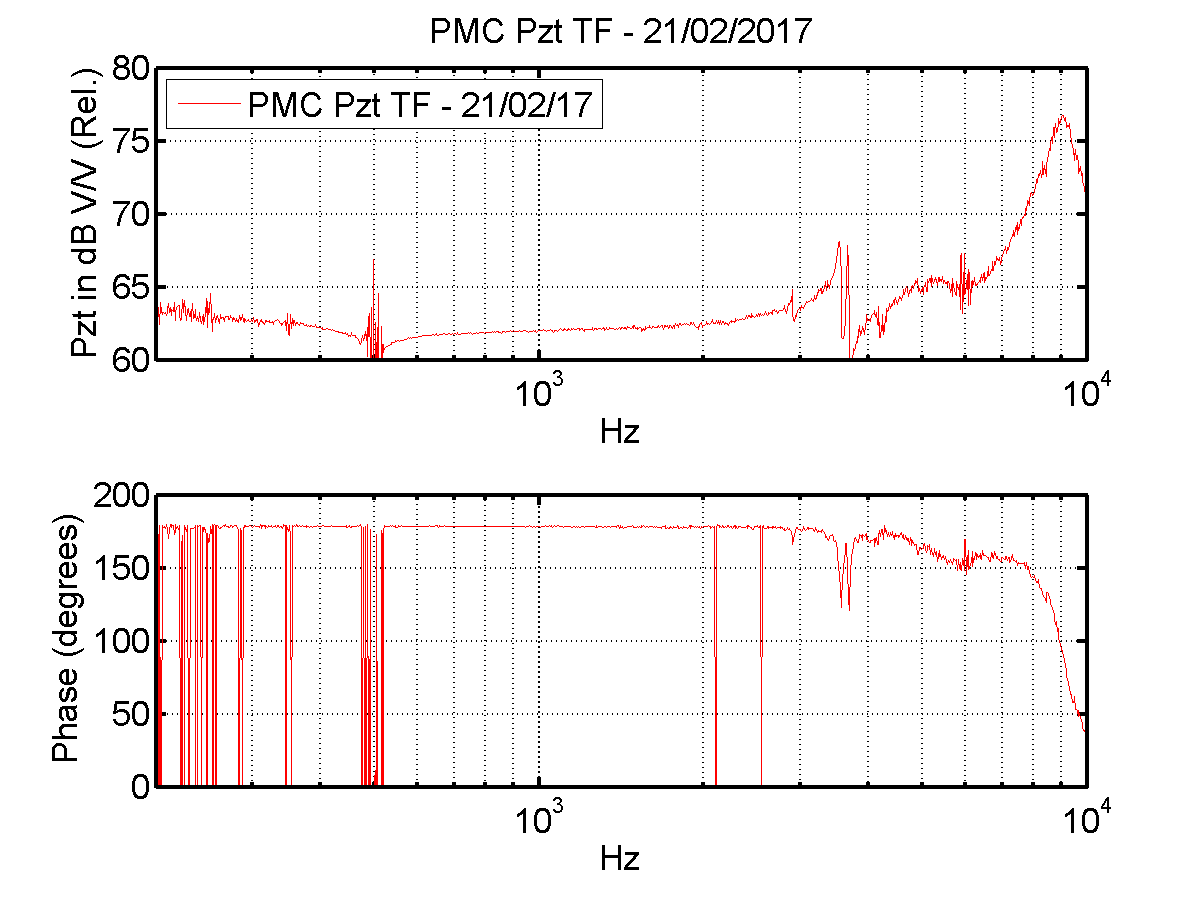
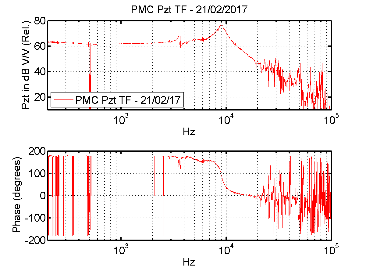
# PMC - Pzt
plot 4/5 give the transfer function of the PMC piezo
a notch 3-4 kHz is present in the rampauto and reduces a bit the associated structure, to be compared with the TF mention in the PMC user manual
plot 6 gives a calibration of the PMMC piezo: 68 MHz/ (70 MHz/V in the user manual)
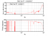
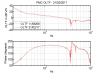
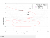
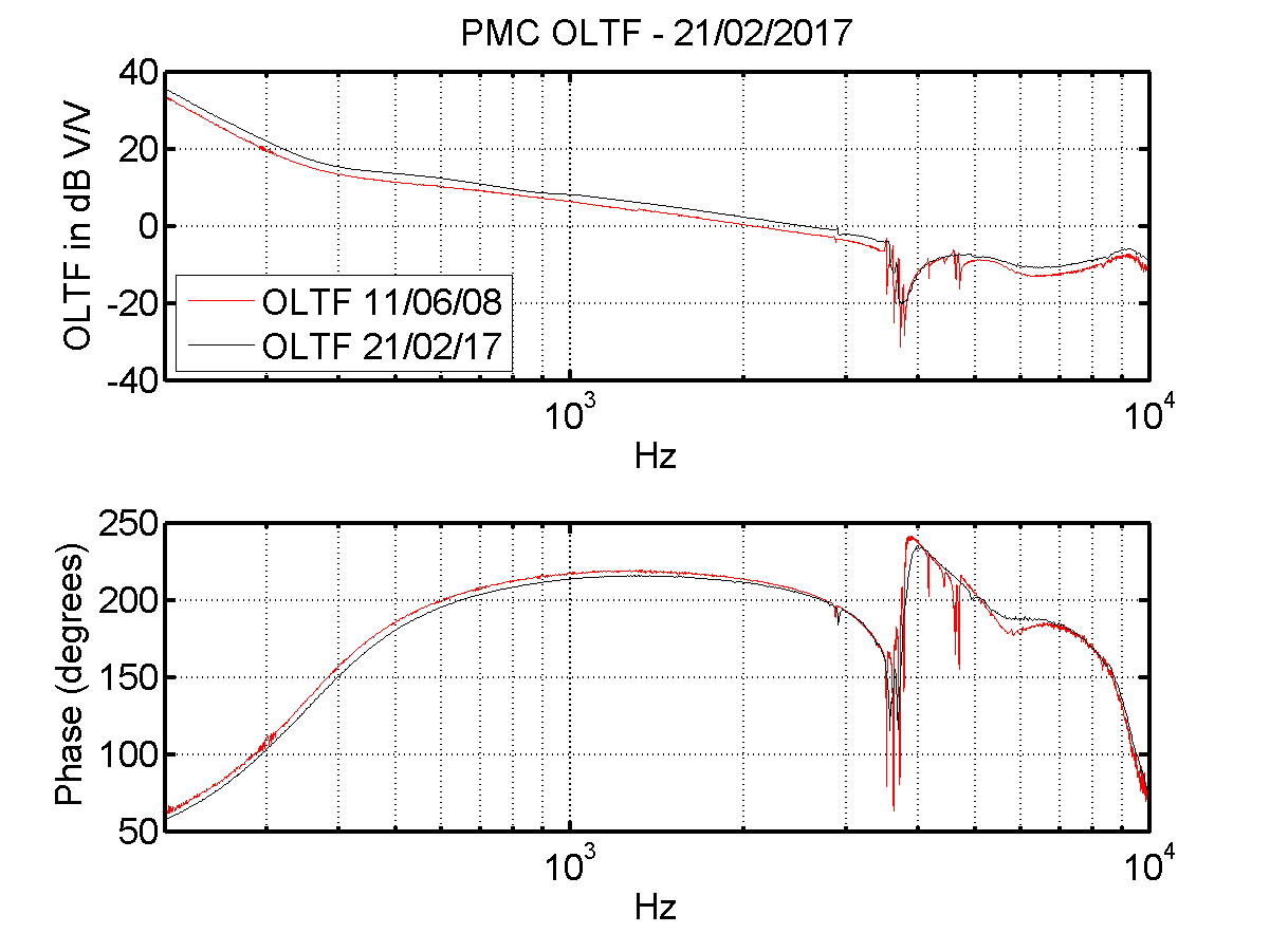
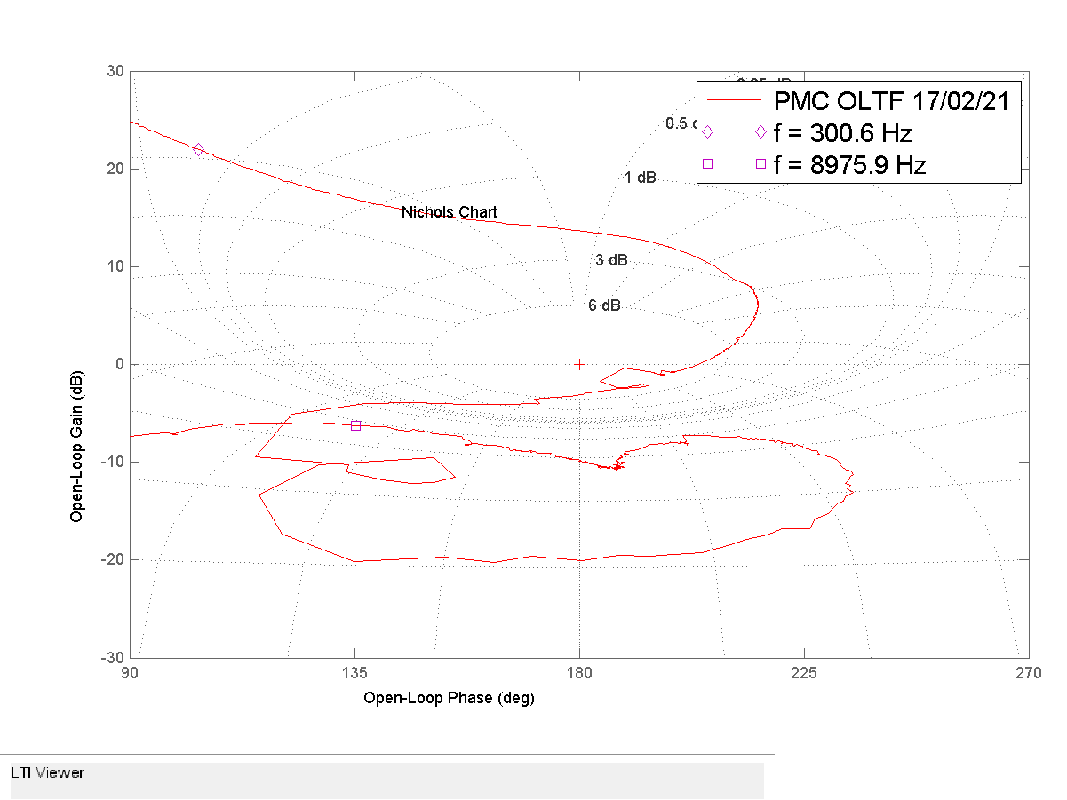
# PMC - OLTF
plot 7/8 gives the OLTF in 2008 (PMC commissioning ) and today, + the Nichols chart to assess the margin stability
the loop features a stability of 16,8 dB which more than enough assuming that the OLTF is well centered using the RF attenuation provided by the remortly controled "dB box".

