Tonight we handed DARM control off to the light transmitted by the two OMCs.
Locking on dark fringe was less stable tonight than over the weekend, we only had a few locks that lasted more than a few minutes. Throughout the night we worked with the BS and NE automatic alignment loops enabled after the transition to dark fringe, and the WI, NI, and WE mirrors on drift control using the dither lines. We tried to perform the trick of reducing the PR F0 Y setpoint by 4 microns and then enabling the AA loops for the PR, but this didn't seem to improve the stability, and we only tried a few times.
We achieved one good lock at dark fringe of a bit longer than one hour. During this lock, we applied a DARM offset of 0.003, and Michal scanned and locked both OMCs. (Calibration people: can we calibrate this DARM offset into picometers?) There is a period of undisturbed data from 20:30 UTC for about ten minutes, which can be used to investigate correlations between the OMC transmitted power and alignment signals, LSC loops, etc. Starting at 20:41 we injected broadband noise for about 90 seconds into DARM to check the B1 DC --> DARM transfer function. To make the handoff, we used a simple offset and gain applied to the B1_DC channel to build an appropriate signal for DARM_INPUT. The gain we used was 1/3000, but this will change with the DARM offset, so for now we'll have to measure this by hand at each lock. A more sophisticated method for conditioning the B1_DC signal has been implemented in the LSC process but will take some time to commission (details to follow). We tried a MICH offset earlier in the evening, but this broke the lock, and in the interest of progress we switched to DARM.
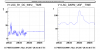
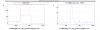
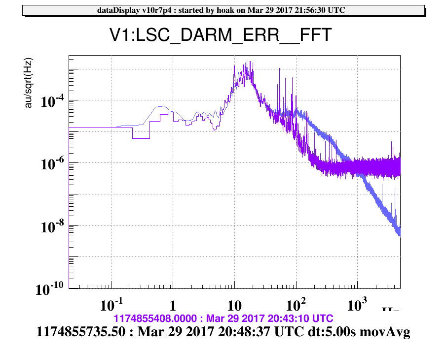
At around 20:45:30 we handed DARM off to the B1_DC signal, see Figure 1. The lock lasted about 3 minutes. Initially the offset was mistuned and the gain increased as the arms were pushed further up the quadratic curve, this was slowly corrected by the UGF servo. The DARM noise on B1_DC was not substantially better than the RF signal, see Figure 2 (purple: DARM on RF; blue: DARM on DC). Part of this excess noise may be due to saturations of the audio channel of the B1 photodiodes, which was railing with a 15Hz cycle, coincident with the tall dither lines in the spectrum. Next time we try the handoff we should reduce the DARM offset a bit and reduce the amplitude of these lines; we can also try locking with the B1s2 signal, which has less light. At high frequency the B1_DC signal is much quieter than the RF signal, as expected.
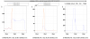
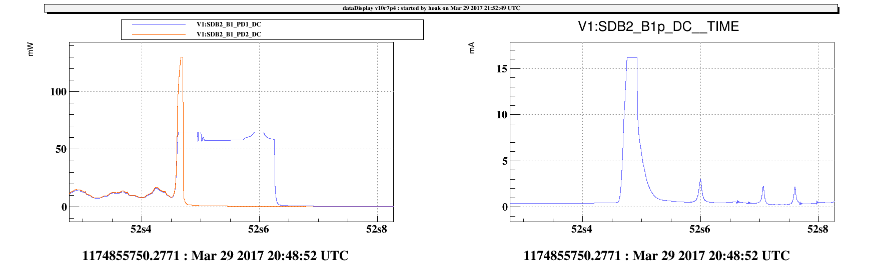
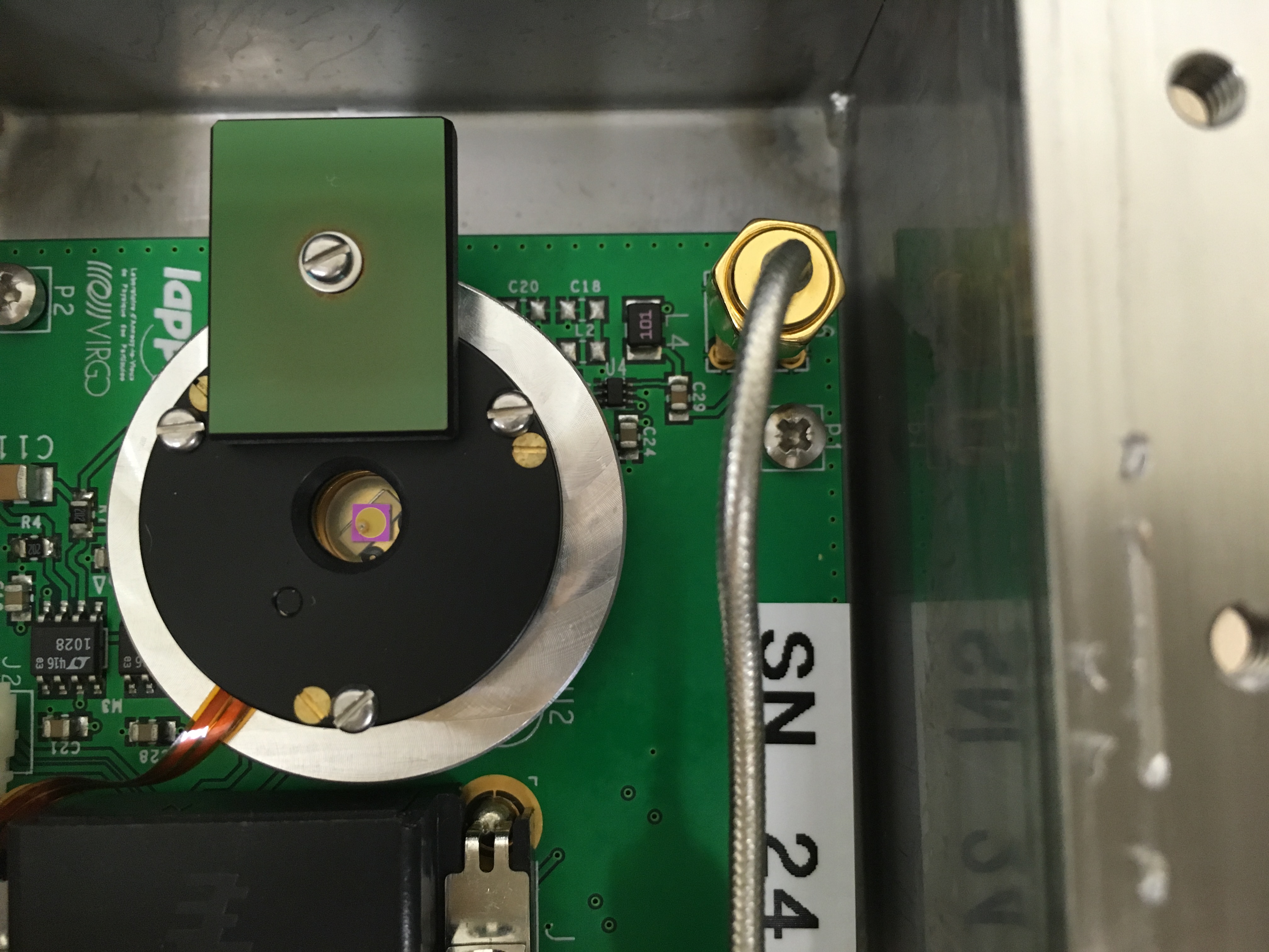
Following the unlock, the Vbias of the B1 PD1 photodiode could not be recovered. In Figure 3, the bright flash from the lockloss caused the B1 PD2 shutter to close (and the photodiode to saturate at 130mW), but for some reason the PD1 signal persisted for about 0.2 seconds following the lockloss. We suspect the shutter for this PD did not close, and the PD may be damaged.
Another problem tonight: the TANGO server for the suspensions crashed a few times. The first two times, Franco and Giovanni restarted the process remotely, but after the third crash around 11:30pm we decided to go home. Responsible parties were notified by email, the process should be fixed before the morning shift. The ITF_LOCK node has been set to DOWN for the night.

