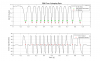
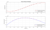
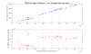
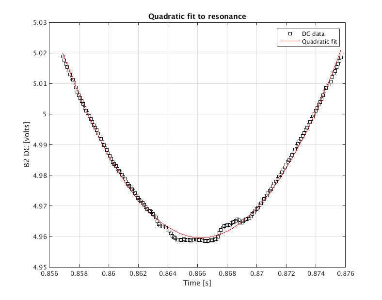
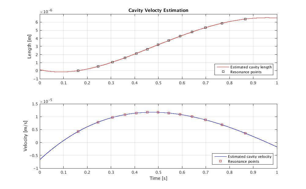
During a period when the PRNI is free-swinging, we collect a chunk of data that includes several resonances, as observed by the B2 photodiode (see Fig 1). The data around the minima are fit with quadratic functions (Fig is an example - this is the right-most resonance in Fig 1), and the minima of these quadratics are taken to be the cavity resonance points, separated in length by 532nm. From these data points we fit the evolution of the cavity length with a 4th-order polynomial (Fig 3) and calculate the velocity.
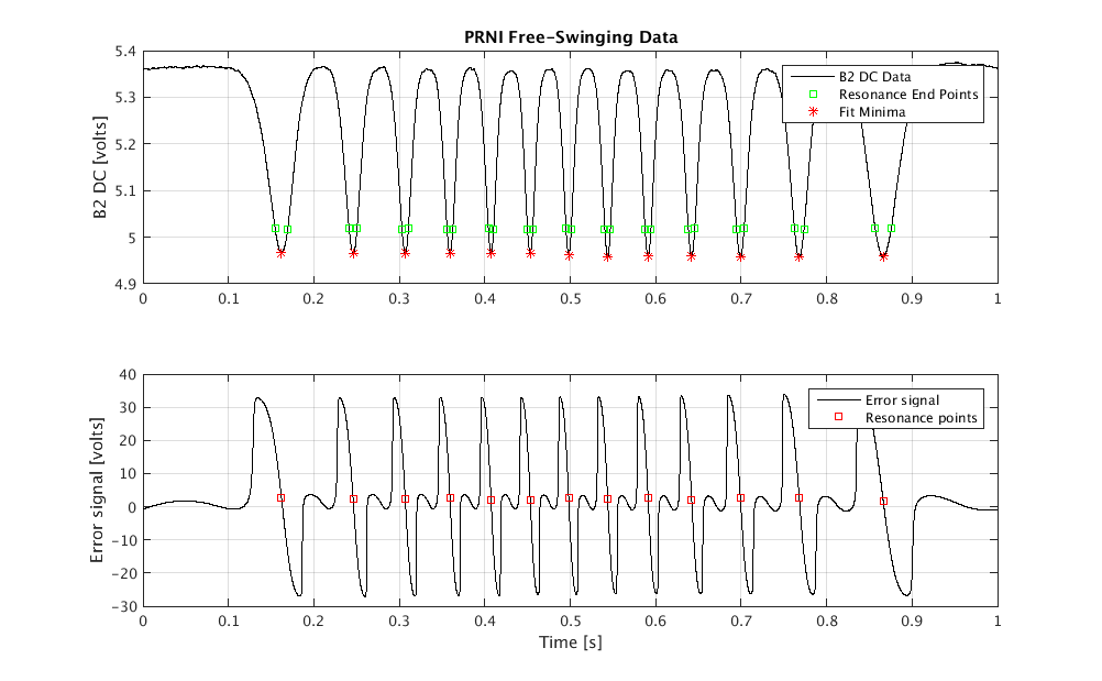
The optical gain, in volts/meter, is the ratio of the slope of the error signal (volts/second) with the cavity velocity (meters/second) around the resonance points. This is shown in the bottom panel of Fig 4, which includes a lot of data points that I collected mostly by hand, from a few different times on Friday afternoon. The calibration of the B2 6MHz signal is roughly 4.5 x 10^8 volts per meter of PRNI length motion.
This is just a first attempt, here are some notes:
I think there's a systematic effect introduced by the quadratic fitting when the velocity is changing rapidly. These tend to be the points clustered around 0.4e-5 m/s, 5.5e8 V/m in the bottom panel of Fig 4.
In Fig 1, you can see a DC offset in the error signal at the resonance points of about 2 volts. If this is a dark offset in the B2 6MHz signal we can easily tune it out.
In Fig 4, the optical gain changes by tens of percent between measurements at different velocities (which are separated in time by up to a few hours). This may be due to changes in the demodulation phase, which changes the overall gain of the sensing path (since we're using a fixed demod phase for all of these measurements). In order to get a good calibration of the error signal and overall loop gain we should collect some free-swinging data immediately before locking the cavity and measuring the noise and loop shape. From there we can estimate the unsuppressed cavity motion, estimate the plant transfer function, and so on.
It would be more robust to drive the cavity length with the marionetta through many fringes, rather than relying on the excited pendulum modes to move the mirrors a few microns back and forth.
It will be interesting to compare the calibration of B2 6MHz to the 131Mhz signal (or the 8MHz, or the 56MHz) and confront these numbers with Finesse simulations.
