Last week on Wednesday and Thursday we pursued the activities of prealignment on SDB1/SDB2/EDB benches.
SDB1 prealignment:
A beam was sent from EDB to match the beam exiting the telescope through the Hartmann dichroic mirror on SDB1, when the SDB1 bench is assumed to be in its nominal position and yaw angle: y(VRS) = 0 mm, thetaZ(VRS)= 0 degree. For this measurement the SDB2 bench was bypassed by turning some optics. Thus the injected beam was going straight from EDB to SDB1, passing through the viewport normally dedicated to B1s1 on the east side of the minitower, and passing through the minilink and its viewport dedicated to the Hartmann beam between the minitower and the detection tower.
The position of the injected beam has been determined with an Optocad simulation and was adjusted on EDB so that the beam passes by two points given by the following coordinates in the EDB local coordinate system (z axis along beam propagation, x axis pointing towards north):
· Point 1: z = 512.5 mm ; x = -28.7 mm
· Point 2: z = -937.5 mm ; x = -37 mm
The beam height is such that the beam is about 100 mm above the EDB table.
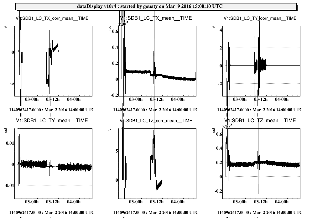
We then adjusted the angular position of SDB1 in yaw (TY) and pitch (TX) in order to get the beam back reflected and superimposed with the injected beam. This should correspond to the nominal angular position of the bench (see SDB1 LVDT signals on Fig.1, and the nominal bench angular positions reported in the table below), with an estimated accuracy for the yaw angle of +/-700 urad (the error bar is dominated by the uncertainty on the beam positioning on EDB).
|
SDB1 dof in local coordinate system |
Nominal angle (mrad) |
|
TX (pitch) |
0.05 |
|
TY (yaw) |
-0.95 |
|
TZ (roll) |
0.2 |
The tuning of the bench angles has been made by acting a bit on one of the marionetta motors (about 10000 steps with the so-called motor “Mario TZ”) and on the bench actuators (typical corrections on TX=0.2 V, TY=0V, TZ=-1.6V) and by adding some little weights on the bench (the used weights are Allen keys and will be replaced soon with appropriate counter weights). The added weights are 46 g in front of the meniscus lens (SDB1 west side) and 4g in front of the OMC support (SDB1 south side). During this operation we found out that one of the marionetta motor, so-called “Mario TX” is malfunctioning (the electrical wiring seems OK as the motor makes noise but it does not move).
After the SDB1 bench position was tuned, we checked with a laser meter the distance between the bench north and south sides and the north and south flanges of the tower:
· SDB1 north – north flange = 1056 mm (same value at north-east and north-west corners)
· SDB1 south – south flange = 1064.5 mm (actually we measured 1064 mm near the south-east corner and 1065 mm near the south-west corner, the two measurement points being separated by about 30 cm)
These values are consistent within ~1mm of accuracy with measurements made several weeks ago (entry 33225) and with the bench position adjustments performed since then.
SDB2 prealignment:
The altitude of the four SDB2 bench corners with respect to the EDB bench has been re-checked using a Leica lever. As already reported in entry 33124, the south side of SDB2 was found to be too high by 1.5 mm with respect to the EDB altitude, while the north side of SDB2 was too low by about 0.5 mm. The resulting roll angle of SDB2 has been corrected by acting on the jacks and adjusting the wire length.
SDB2 should now be horizontal and at its nominal height. However during this tuning operation we found that one of the jack (SW corner) was reaching the end of its range. Accordingly we decided to dismount it in order to modify it. The modified jack will be mounted back in the near future and we will cross-check again the bench altitude after this is done.
The lateral positions of the bench (X and Y in VRS) have also been adjusted in order to better align the SDB2 bench with respect to the multi-sas axis.
After these adjustments, the SDB2 bench Y position (VRS) and yaw angle have been measured using two beams sent from EDB: one beam passing through the B1s1 viewport (this is the beam mentioned above) and the other one passing through the B1 viewport. The positions of these two beams measured on SDB2 give coherent results, namely:
· Y = -7.5 mm +- 0.25 mm (SDB2 center in VRS, the error bar is dominated by the beam positioning measurement)
· TZ = -5.3 mrad (yaw angle, in VRS)
It can be noticed at the TZ angle is quite far from 0. This will be corrected after the modified jack is put in place.