IMC throughput measurement
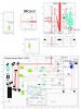
We have installed a beam splitter (T=80%/R=20%) in front of IMC_Tra photodiode in order to measure directly the power of this pickoff beam (see first picture).
We have measured 830uW on the power meter (which corresponds to 7.44V on IMC_Tra). Using the direct measurement from the power meter (Ophir low power head) and considering that the transmission of SIB1_M6 mirror has been measured by LMA to be 734ppm (T_M6).
We can estimate the power we have at the output of the Faraday isolator using the following expression:
Pout_FI = P_measured *(1/R_bs)/(T_M6)
Considering all SIB1 optics on the beam path between the IMC cavity and SIB1_M6 mirror (M11 reflectivity, L3, L2, Faraday isolator throughput) T_SIB1, the output power of the IMC cavity is:
Pout_IMC = P_out_FI/T_SIB1 Where T_SIB1 = R_M11*T_L3*T_L2*T_FI_Pol*T_FI
With 0.2% error on each coating and 2% error on the Faraday isolator transmission, we find T_SIB1 = 0.955 - /+ 0.019.
We have also to take into account the matching on the IMC cavity (see logentry # 31548). Thus, the power coupled in the cavity is: P_coupl_IMC = Pout_EIB*Matching
Thus, the total IMC cavity throughput losses are: IMC_Throughput_losses= 1- Pout_IMC/P_coupl_IMC IMC_Throughput_losses = 1 – ( P_measured . 1/R_bs )/ (Pout_EIB * Matching * T_SIB1 * T_M6 ). For the final estimation, we also considered some errors in the measurement process. These errors are reported in the following table.
Thus, IMC throughput losses are:
IMC_Throughput_losses= 17.66% +/- 3.14%
Meaning that the cavity throughput is T = 82.34% +/- 3.14%
Using this number and the equation (4) given on page 5 of VIR-0232A-10, we can compute the cavity round trip losses.
T = 4 *T1*T2 / ( T1 + T2 + Lrt )^2
T1: IMC cavity input mirror transmissivity.
T2: IMC cavity input mirror transmissivity.
Lrt: round trip losses.
With : T1 = 2410ppm +/- 83 and T2 = 2400ppm +/-41 (for the current dihedron)
Lrt = 490 ppm +/- 165ppm
Then, we can deduce the Finesse F from the expression F = 2*pi / (T1 + T2 + Lrt)
And we find: F = 1185 +/- 30
Finally, the IMC cavity pole fp is:
fp = FSR/2F where the FSR=c/2*Limc with Limc=143.42m (FSR= 1.045155 MHz).
fp = 441.7 Hz +/- 11Hz
IMC cavity pole measurement
We have used the same technique than the one presented in VIR-0232A-10.
We have injected a white noise at the level of the slave laser pumping diodes power supplies.
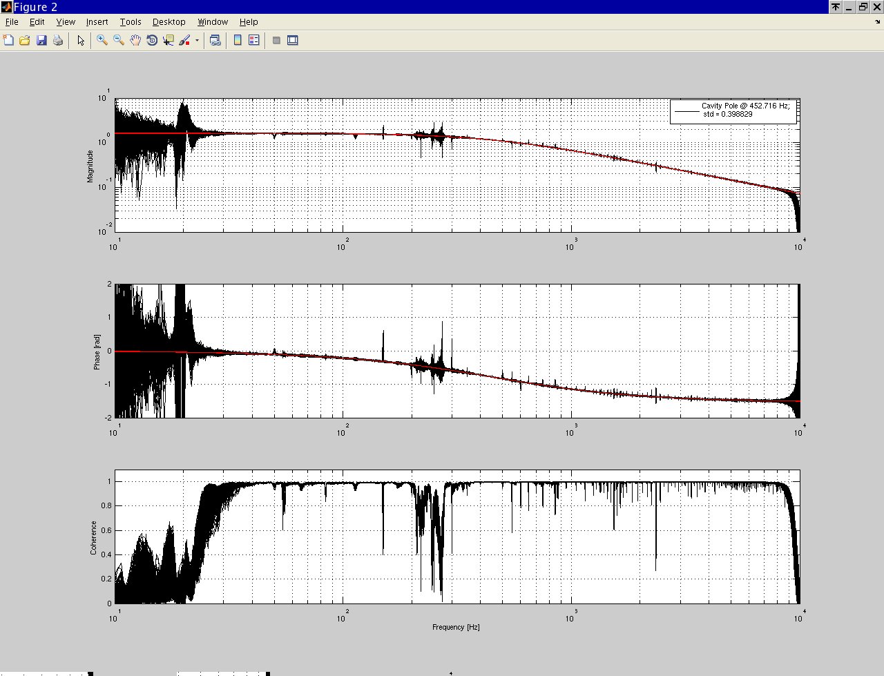
Some measurements are already reported in the logentry # 31548. On figure 2, one can see the magnitude the phase and the coherence between IMC_Tra and PMC_DT_DC photodiodes.
The TF between IMC_TRA_DC and PMC_DT_DC has been fitted in order to extract the pole frequency.
Moreover in order to increase the measurement confidence a statistical approach has been used by measuring the pole frequency during the entire night, in which the noise has been left on.
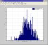
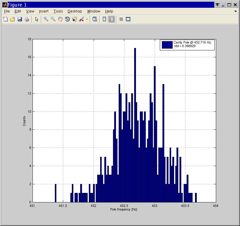
In Figure 3 the pole frequency distribution is visible this has been obtained by fitting 120 sec of data in the frequency region in which the coherence is larger than 0.7.
The frequency of the pole results to be 452.7 +/- 2 Hz. These measurements looks more accurate respect to what was obtained measuring the throughput of the cavity.
Using the equations provided in VIR-0232A-10, we can also estimate the Finesse and the round trip losses of the cavity.
Finesse = 1156 +/- 5 (Note that this number is corresponding quite well to what has been found by Henrich (see logentry #31557)).
Lrt = 625ppm +/- 92ppm
Thoughput= 77%+/- 3.4%
Taking account of error bars, the results are compatible with what have been estimated measuring the throughput but in both cases the error is quite big,
Conclusion
It seems that the round trip losses are higher than what we were expecting (ranging from 350 to 700ppm instead of 100ppm). Investigations are currently on-going to understand what the origin of the extra losses is. It is likely that it is coming from the IMC end mirror since we know that the mirror had been contaminated during the installation phase (see logentries #31341 and#31362) and that the in-situ cleaning reduced the surface cleanliness but was still not perfect.
We are currently studying the round trip losses change function of the beam position on the IMC end mirror.