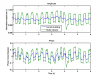
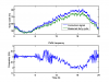
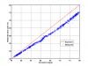
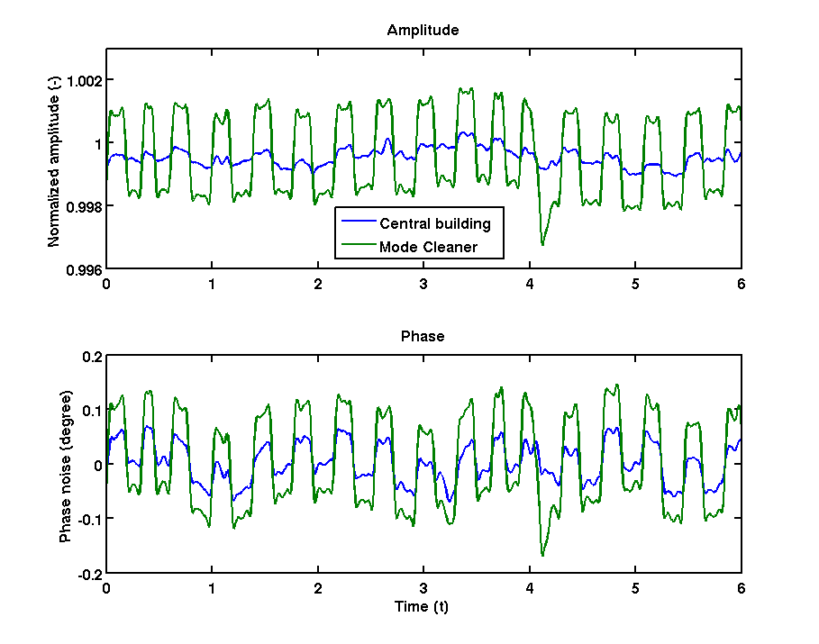
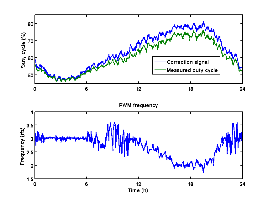
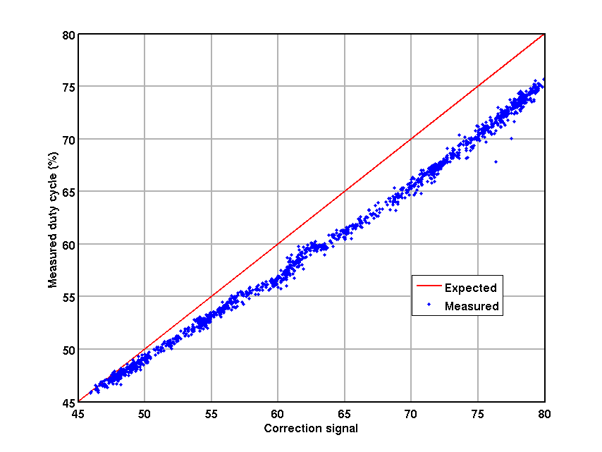
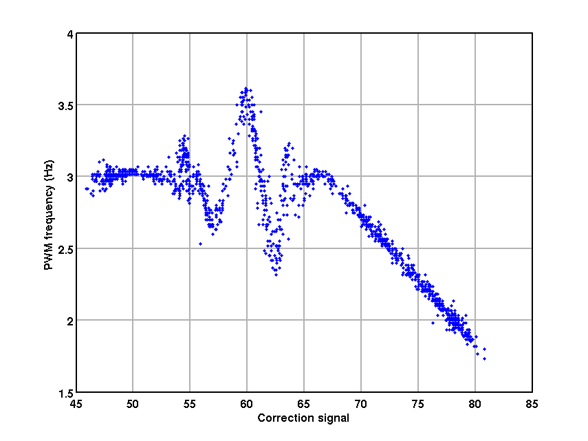
To check again that this on/off signal is indeed caused by the mode cleaner heating, I performed the same analysis over 24 hours, in sections of one minute at a time. For each section, the pulse-width-modulation frequency and duty cycle is determined. Fig 2 compares these signals with the correction signal of the mode cleaner heating (IMAC_MC2_Loop_1_Main_ActiveOut). Fig 3 shows that the correction signal translated almost directly to a duty cycle in percent (there might be some bias in the analysis). Fig 4 shows a strange feature of the PWM controller, which changes not only the duty cycle but also the frequency as a function of the correction. It is interesting to see that at high corrections the frequency seems to decrease linearly. In the past we saw the opposite (frequency increases linearly with correction), but that was probably during much better weather when the correction signal was below 50. It is probable that this figure is symmetric around 50 percent.
These observations are still consistent with our old hypothesis that the switching of the load in the MC pollutes the IPS line in the main-building, which is then coupled to the mirrors via magnetic noise of some big machines that are on the IPS. That we see contamination in the MC is expected, since the current of the heater will cause a small voltage drop over the nonzero resistance of the wires from the technical building to the MC. That we see the same in the CB is not expected, since the transformator in the technical building (which delivers 1 MW) should be considered an ideal voltage source and the different buildings should be connected in a 'star'-configuration. It might be that there is some inductive coupling between the various wires. Maximo is preparing a dedicated test, in which only the MC building will be powered by the diesel generator.

"That we see the same in the CB is not expected, since the transformator in the technical building (which delivers 1 MW) should be considered an ideal voltage source and the different buildings should be connected in a 'star'-configuration."
comment:
If instead the transformer is not ideal, but has its internal series resistance and inductance, we can think that a drop (in voltage) and a shift (in phase) will occur even if the buildings are connected in a "star" configuration.