The improvements are the following:
- We use InGaAs photodiodes instead of silicon.
It is less sensitive to temperature changes, and the maximum input power is higher (50 mW instead of 5 mW)
- We use beam-splitter cubes instead of blades.
It is less sensitive to humidity in air. Beam-splitter blades also polirise the beam a bit, far more than the cubes.
- The angles of incidence of the beams on opticals components should be 45 degrees.
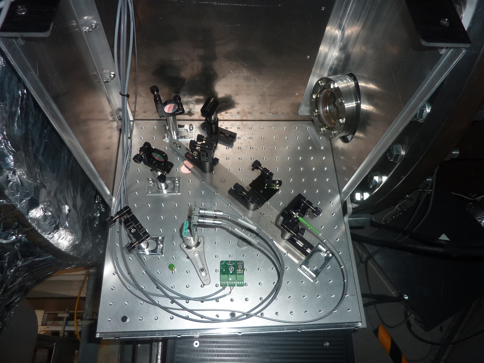
On the setup :
A laser source, wavelength = 1047nm, s polarized,
a polarized cube (thorlabs PBS123) to remove every trace of p polarized
an unpolarized beam splitter cube (thorlabs BS074) 90:10
two 100% mirrors (thorlabs BB1E03)
an unpolarized beam splitter cube (thorlabs BS062) 70:30
an unpolarized beam splitter cube (thorlabs BS065) 70:30
two photodiodes InGaAs (excelitas c 36 165)
5 beam dumps (standa)
photodiodes are supplied in power by a power-suppliers (rohde&schartz hmp4040), their data are read by ADC2378

Modification of covers of the benches of WE and NE PCAL: plastic elements and matte black aluminium foil.
The covers of the PCal benches have been modified in order to reduce friction between aluminium parts when opening/closing the benches (generating aluminium dusts on the benches). The aluminium parts have been machined and some plastic parts have been added on both the fixed and the mobile parts of the covers.
In addition, matte black aluminium foil has been tappered inside the covers in order to reduce scattering of ambient light and un-dumped ghost beams.
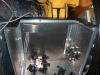
- Picture 1 shows the fixed part, with the new plastic elements (in black).
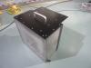
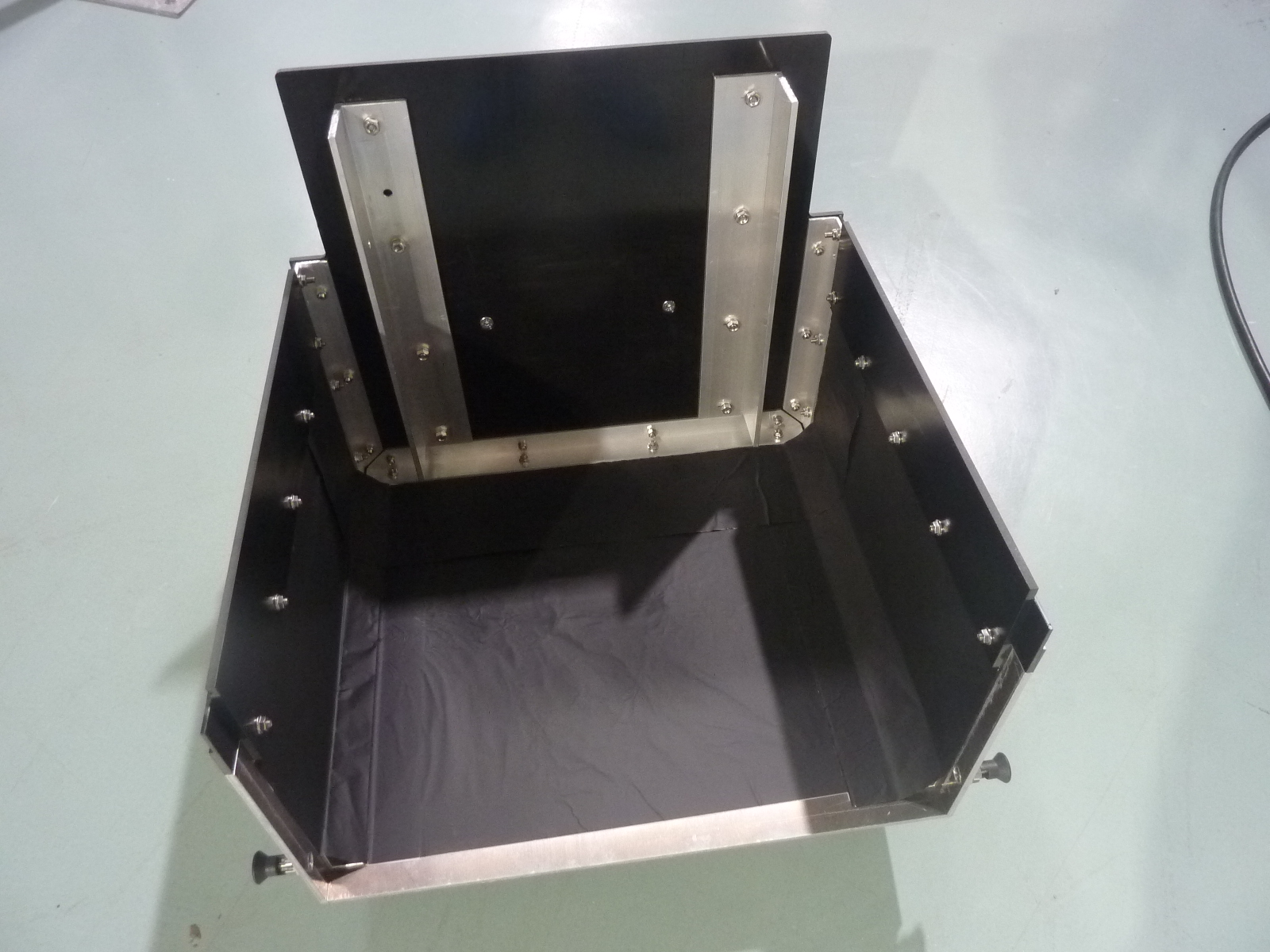
- Picture 2 shows an external view of the mobile cover, with new plastic elements on the side and on the top.
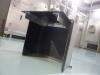
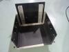
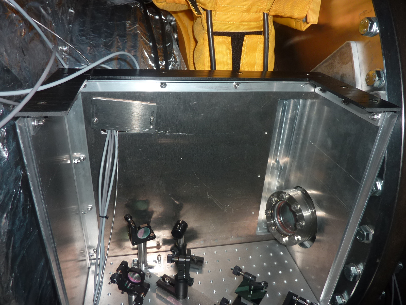
- Pictures 3 and 4 show internal views of the the mobile cover, with new plastic elements and with matte black aluminium foil (BKF12 from Thorlabs) tappered on the three vertical panels of the cover.
Some black aluminium foil has also been tappered on the vertical back panel of the fixed part of WE Tx bench (before remounting the optics). No foil has been added yet inside the fixed parts of the other benches (WE Rx, NE Tx and NE Rx).
This activity was done from Tuesday 27 April 18h LT to Thursday 29 April noon.
WE PCAL RACK
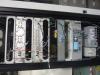
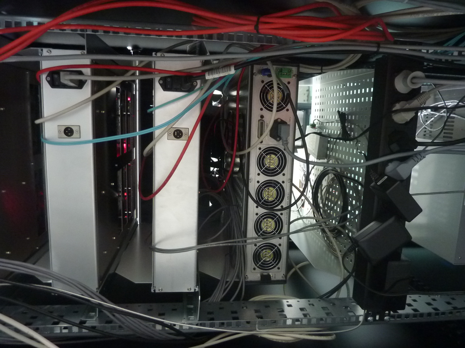
Picture 1 shows the rack with WE PCal electronics modules installed (it was not yet fully cabled):
- DaqBox 49 with 4 mezzanines: ADC/DAC/ADC/fastDAC
- PCal laser driver (1047 nm, 3 W). Serial number 1161394. Driver was set to APC mode (power control) when switched on.
- relay box (to switch on/off a LED connected on IRIG-B signal from the WE TDBox)*
- Netcom for RS232 monitoring and control (to connect calibration powermeters on port 1 and PCal laser driver on port 2, still to be connected). It is called ethcali2.
- Hameg power supply (to power InGaAs Pd pre-ampli and Vbias with -12 V and +12 V DC). It is called hameg26. The two other channels will be used to power the electronics of the LIGO-style integrating spheres to be installed on the Rx benches later (-15 V and +15 V DC).
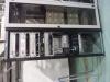
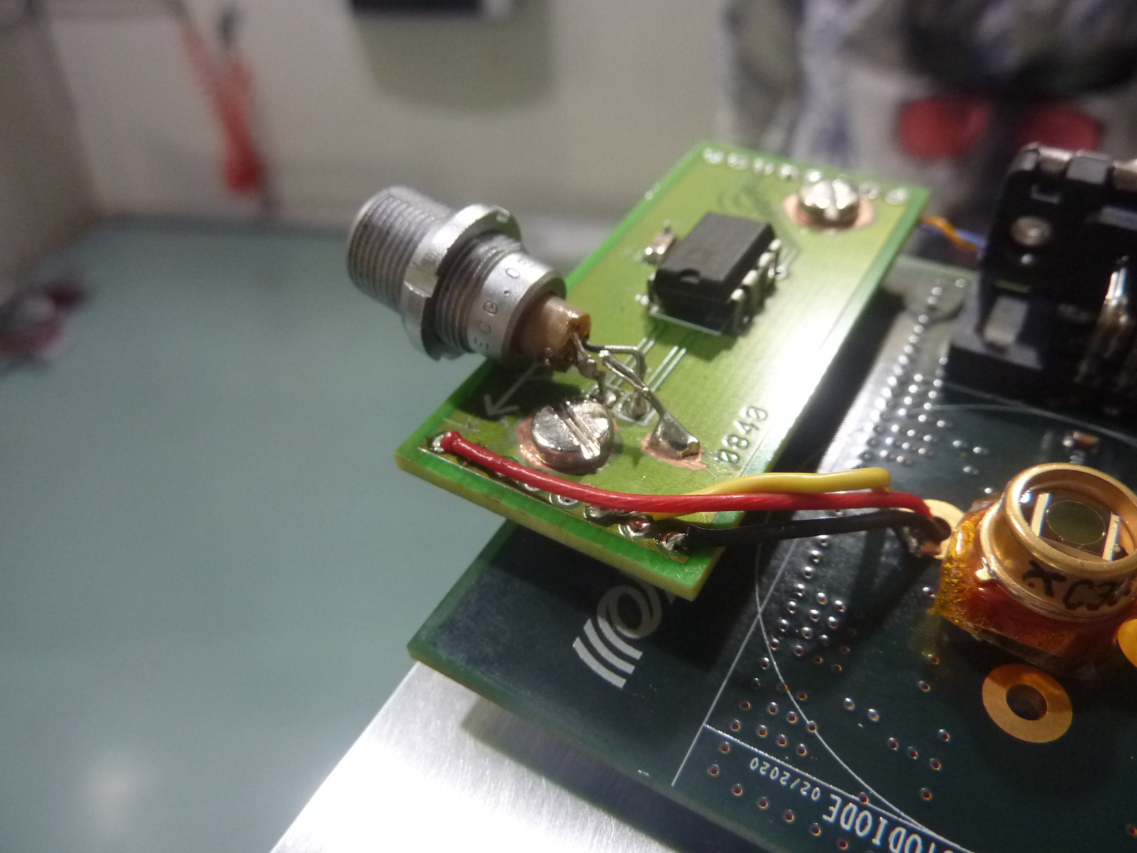
On the InGaAs photodiode preamplifier prototypes installed on the WE Tx bench, there is a mezzanine to convert the DC single-ended output to differential output. The connector welding broke (Tx_PD1, see picture 2) during installation and was repaired by EGO electronics (thanks Gianmatteo).
WE PCAL miscellaneous information
Some information on the setup installed last week (WE PCal):
- since the PCal signals have a large DC offset (from laser DC power), the ADC2378 mezzanines used for PCal have been changed compared to O3 to profit from the improvements of the new ADC production (reduction of 1/f noise in presence of DC offset in particular).
- photodiodes Tx_PD1 and Tx_PD2 are 3 mm diameter InGaAs photodiodes from Excelitas (same as DET photodiodes), mounted on 80 mA preamplifiers from DET with slight modifications, as described below. The resistors mounted on the pre-amplifiers are 'low-noise' in order to reduce the 1/f noise that was present in some previous O3 preamplifiers.
- photodiode Tx_PD1 (the one in transmission of last splitter, with ~50 mW incident power when laser output is 2 W):
- DC single-ended output is converted to differential in the small mezzanine added on top of the preampli, and it is connected to an ADC2378 channel with a 12 m cable (LEMO3 connectors).
- Audio single-ended output is connected to ADC2378 with a 12 m cable (from subd15 on pre-ampli to LEMO3 on ADC).
- pre-amplifier powering and Vbias are coming from -12 V and +12 V from Hameg power supply in the rack, through a 12 m long cable (the tensions have been tuned to 12 V for now, not slightly higher in order to compensate for voltage drop in the cables). Connected in parallel of Tx_PD2.
- Since the Audio channel is connected, the DC analog output must have a non flat frequency response, with a pole/zero around few Hz (similar as described in entry 51180 ).
- photodiode Tx_PD2 (the one in reflection of last splitter, with ~20 mW incident power when laser output is 2 W):
- DC single-ended output is converted to differential in the small mezzanine added on top of the preampli, and it is connected to an ADC2378 channel with a 12 m cable (LEMO3 connectors).
- Audio channel disconnected on the preamplifier.
- pre-amplifier powering and Vbias are coming from -12 V and +12 V from Hameg power supply in the rack, through a 12 m long cable (the tensions have been tuned to 12 V for now, not slightly higher in order to compensate for voltage drop in the cables). Connected in parallel of Tx_PD1.
- Since the Audio channel is disconnected, the DC analog output should have a rather flat frequency response from DC to few 10's kHz.
- photodiode Rx_PD1 (the one on the reflection bench)
- it is the same Si photodiode as used during O3 (1 cm^2) with the Vbias of 4.5 V provided by a DAC1955 channel and its readout done reading the voltage around a 1 kOhm series resistor on the PCB (with the ADC2378 channel and its 2 kOmh input impedance).
- PSD Rx_PSD1
- same as during O3, Vbias of 4.5 V provided by DAC1955 channel
- beam was not aligned on the PSD, still to be checked/done.
We could not test the remote control of the laser power via the fastDAC (waiting for reconfiguration of TOLM paths of ALS data). All measurements were done with the laser power set manually from front panel. Before we left, the laser has been set to Remote mode and the cable from fastDAC to laser driver plugged (from the fastDAC single-ended output to the driver BNC input directly). To monitor the fastDAC output, its differential output has been connected to an ADC2378 channel.
Three devices have been connected on the Ethernet network at WE. They have been connected to ports 10, 11 and 12 of the switch number 2:
- Netcom RS232-Ethernet (ethcali2)
- Relay module (relaisdet1)
- Hameg power supply (hameg26)

This activity on NE PCal was done on Wednesday 28th April afternoon (14h to 17h LT).
NE PCAL RACK
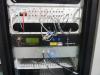
Pictures 1, 2 and 3 show the rack with NE PCal electronics modules installed (it was not yet fully cabled), with the same configuration as during O3:
- DaqBox 35 with 4 mezzanines: ADC/DAC/ADC/fastDAC
- PCal laser driver (1047 nm, 3 W). Serial number 1170127. Driver was set to APC mode (power control) when switched on.
- relay box (to switch on/off a LED connected on IRIG-B signal from the WE TDBox).
- Netcom for RS232 monitoring and control (to connect calibration powermeters on port 1 and PCal laser driver on port 2, still to be connected). It is called ethcali1.
- (not yet Hameg power supply since still using the O3 optical layout and photodiodes).
Two devices have been connected on the Ethernet network at NE. They have been connected to ports 11 and 12 of the switch number 2:
- Netcom RS232-Ethernet (ethcali1).
- Relay module (Pcal-NE).
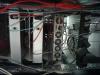
NE PCAL OPTICS
The optics and photodiodes are the same as during O3. The optical fiber (11 m) from the laser driver has been reconnected onto the collimator (see picture 4). The beam alignment was found to be good without large tunings. The same Si photodiodes as during O3 are still being used, as well as BSX11 mirrors.
The alignment of the Rx photodiode (1 cm^2) was correct and hence not modified. Note that the NE tower was being vented during that period (see logbook 51534 ).
