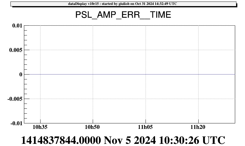
This morning at 10h10 L.T I started a new version (v2r1p0) of cmLaserAmp_thin to solve the problem of flat signals that appeared with the installation of the new chiller. The application is up and running, and the error in PSL_AMP_ERR signal dissappered (see image).

This morning, starting from 9h30 LT, I moved and restarted the following servers from /virgoDev to /virgoApp.
Femto (new version v6r8)
SL_TempController (new version v2r3)
TCSChillerGUA (new version v2r3)
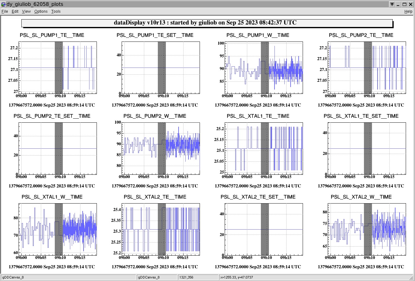
Since yesterday I started doing tests to improve the functioning of the SL_TempController server. In the past (see #elog61576), after a few months of operation, the server showed fake temperature increases on the slave laser. The new version (v2r3), launched today in test at 12:09 LT, was created to eliminate this problem and improve data quality. In the picture, it's possible to see the different quality of the signal provided by the v2r2 version and the v2r3 version.

This afternoon I replaced the ethernet bridge in the title with a spare one with IP: 192.168.226.43 in EERoom because it did not answer anymore the "ping" command. This bridge is used by SL_TempController server to read data from Slave Laser. All data is now available again in the Virgo DAQ.
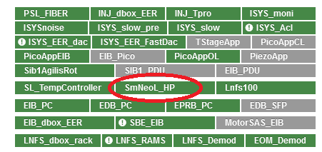
This morning I moved from Tango to VPM the TangoCmLaserAmp server (now called SmNeoL_HP see picture), that was running without problems on Tango since few years. Now all channels are already available on DAQ.

As a follow up of the EOM 81.5 MHz installation yesterday morning we have updated the Lnfs100 server to the v4r1 version of the PyLNFS100 software.
This version:
- add the tuning of the 81.5 MHz frequency into the
SETFREQ command handler as:81.5MHz = 8 * 3 * 13 * / 4 (actually in the code:new_freq_81_5 = new_freq_8 / 8.0 * 78) add the command SET81AMPL in order to set the81.5 MHz amplitude
Also this version, in the frame of removal of the remaining critical dependencies on Tango within the Automation (see 56721), has merged in the direct LNFS interfacing functionalities of the Lnfs100 Tango server which is now dismissed (and removed from the INJ Tango config).
To proceed in putting in operation the new version we have:
- Put the 2nd LNFS into remote control mode (It has always been on local mode so far)
- Rebooted the ethernet/serial bridge connecting both LNFS boxes
- Updated the Lnfs100.cfg by inserting the HOST and PORT for both devices, namely:
- HOST1 192.168.226.45
- HOST2 192.168.226.45
- PORT1 2001
- PORT2 2011
Once done, after few fixes in the code we had the server up and running and then we checked the availability of the data into the DAQ. The existing channels naming for the 1st LNFS remain the same, and for the 2nd LNFS the "_2_" prefix has been added. See Fig. 1.
We checked then the proper behaviour of the new functionalities by running the SETFREQ and SET81AMPL commands from ipython. Results are shown in Fig. 2 and 3.
For finalizing the tests it would be advisable trigger an FModErr cycle from the Automation INJ_MAIN node. This has been discussed and provisionally scheduled for this Friday.


Today the INJ_MAIN node was updated in order to implement the following:
- check if the ML thermal correction is outside range, in order not to lock the RFC on a wrong fringe: this is done before going to IMC_RESTORED, in the dedicated state CHECK_THERMAL_CORR, meaning that it is done every time we "recover" the injection after an unlock of the ITF or the RFC (when standalone);
- save the last value of the thermal correction, before opening the RFC loop: this is only done in the main Lock Acquisition path, and it is asked by ITF_LOCK during the ACQUIRE_CARM_TO_MC state; this makes the INJ_MAIN node to cycle through FMODERR_TUNED -> SAVE_THERMAL_CORR -> FMODERR_TUNED, without any effect on the Lock Acquisition itself, but maybe a delay of a couple of seconds;
- revert the rough FmodErr tuning from the loop (FMODERR_TUNING_LOOP state, with the IMC locked) to the old-style calibrated movement of the MC mirror with the IMC unlocked (in principle much faster, FMODERR_TUNING_MC_Z state): most of the code is done and a first calibration has been made; what is left is to work out a couple of minor issues in the code (offline) and a test of the procedure (online, ASAP); the current method is unaffected as they each live in their own state so it will be sufficient to change the relevant request in the FmodErr path.
The new layout of the INJ_MAIN node is attached.

The new version (v2r0) has been made default in VPM and the server restarted from there.
To be tested at the first occasion.
Today we tested the fine tuning of the FmodErr signal, which works by changing directly the modulation frequencies (6 MHz, 8 MHz, 56 MHz) on the LNFS, instead of moving the MC mirror every time; this, when only small changes are needed, will improve both the speed and the accuracy of the tuning, while for bigger changes we will still move the MC mirror first, and then do the fine tuning with the LNFS:
-
we first acted on the LNFS by hand, using the script
/virgoDev/Automation/scripts/set_LNFS_freq.py: this script uses the 8 MHz nominal frequency as a reference, a delta frequency we want it to move by, and a maximum overall deviation from such reference; it will change such frequency and rescale the other ones (6 MHz and 56 MHz) accordingly; - as a safety measure, if the overall deviation from reference is too big, the reference value wiil be set again; at this point, the tuning by moving the MC mirror will be necessary, before another attempt;
- we did not observe any misbehaviour, and we tested this both offline and in-lock, without consequence;
-
we did a preliminary calibration in Hz of the usual
INJ_FmodErr_ACpsignal which we use as a sensor of the mistuning; -
after this, we modified the logic of the
INJ_MAINAutomation node in order to implement this novelty (using the same script), and everything still lives in theFMODERR_TUNINGstate as before: if the needed tuning is small, the LNFS method will be used, otherwise the MC will be moved; the logic takes care of doing a fine tuning after the MC tuning, and also in case of the reset to the reference frequency vaues; - the next steps will be to monitor the performance of the macro over time, and to introduce a routine (probably as a new state) to calibrate automatically (and with more precision) the error signal in Hz.
A note about the frequency monitoring: as can be seen in Figure 1, the phase measured with the demodulation board next to the LNFS starts to wrap around at the moment the frequency is moved away from the nominal value, this is expected. Note that there is a frequency difference between the local oscillator in the FPGA of the board and the true modulation frequency, which is already compensated for in the LNFS_Demod process. Since we now have a demodulation frequency which will change slightly for every lock, this correction becomes a bit arbitrary, and can be removed.
The modulation frequency can calculated by taking the 2-sample difference of the phase, correcting for potential wrapping around, and multiplying by -fsample/(2*pi), see attached script and Figure 2. By averaging this signal, an accurate measurement of the modulation frequency can be made relative to the demodulation frequency. It would be good to calculate this online.
One issue seems that the channels INJ_LNFS_FREQ1/2/3 seem to be not very accurate. I guess this is due to the limited precision of 32 bit float with which SMS channels are stored in the frames, which leads to a resolution of about 0.7 Hz for the 6MHz frequency and 6.7 Hz for the 56MHz. It would be nice to store these frequencies as doubles, but I am not sure that is possible.


As noticed by the commissioning crew, the phase-jumps were not due to the LNFS's PLL signal level (marginally on the low side), also because this configuration was used in the last years (and during the whole O2-run) without any problem.
Nevertheless today we went in the Injection Electronic Room (IER = "piscina") to measure the 10MHz signal sent from DAQ to the LNFS's PLL input as reference clock.
As visible (photo 1) the signal is a TTL 0-5V signal, not an AC-coupled LV-CMOS as thought.
Plugging it on a 50 Ohm load (AC-coupled scope) the amplitude is reduced a little bit (0-4V), not halved (photo 2), so the source impedance should be "near-zero" Ohm.
Measuring it on a 50 Ohm Spectrum Analyzer (via a DC-block capacitor) give a RF fundamental level of +18dBm (photo 3); considering the wasted power into harmonics, we can assume +20dBm (100mW/50Ohm) of power.
We then prepared a male-female BNC box with a series capacitor (0.1uF) as DC-block and a raw PI attenuator (100 Ohm, 56 Ohm, 100 Ohm); the level on the output is that way reduced to +9dBm on the fundamental, and plugging it on the LNFS PLL input we have over than 3dB (actually measured) of margin before an unlock (was previously 2dB).
The monitored PLL signal level is now increased from 9.9 to 11.6 (photo 4)
Extract from LNFS manual: "Ext Ref SMA input fo r the external 10 MHz reference. This input port has an impedance of 50 ohms. The external reference provided should be at10 MHz +/- 0.1 Hz with a level of +10 to +15 dBm."
We can see (photo 5) the spectrum and level of the signal as sent to the LNFS using the new adapter/box.


This flags will help us to understand whether the "jumps" we see on the DAQ_LNFS_56/6MHz_phi are directly related with the PLL being on/off or not. What we have experienced these two last days is that everytime that there are such big jumps, we need to retune the demodulation phases, even though the modulation phase is supposed to compensate for these phase jumps (*phi_Corr*). Figure 1 shows the trend of the phases of B7 and B8 6MHz, B4 56MHz and the RFC 6MHz for the last two days.

The new parameters now monitored and available as channels on the DAQ are:
- INJ_LNFS_REF: Power level of external reference signal. Valid range +10 to +16 dBm.
- INJ_LNFS_LOCK: Voltage of the lock detector. Valid range is 0.2 to 0.35 V.
- INJ_LNFS_PLL: Tuning port voltage on the oscillator. Valid range is +/-5 V
If the PLL is disabled then those values are not generated anymore by the LNFS. The choice has bee that, in this case, those channels take the fake value 20 in order to be well detected as out of range. (See Fig. 1).
A new flag LNFS has been added to the DMS which detect when one of those channels is out of range or the status of the Lnfs100 server (INJ_LNFS_INJLnfs100LNFS_State) is not ON (corresponding to 0, see https://logbook.virgo-gw.eu/virgo/?r=35618)
To be noted that the value of REF is marginal on the lower side of the valid range (See Fig. 2). This may be related to the spontaneous unlock (and corresponding change of phases) has been experienced in the past. It seems that the power level of external reference signal could be increased (since an attenuator is on the chain) and this will be possibly soon implemented.


This flags will help us to understand whether the "jumps" we see on the DAQ_LNFS_56/6MHz_phi are directly related with the PLL being on/off or not. What we have experienced these two last days is that everytime that there are such big jumps, we need to retune the demodulation phases, even though the modulation phase is supposed to compensate for these phase jumps (*phi_Corr*). Figure 1 shows the trend of the phases of B7 and B8 6MHz, B4 56MHz and the RFC 6MHz for the last two days.
As noticed by the commissioning crew, the phase-jumps were not due to the LNFS's PLL signal level (marginally on the low side), also because this configuration was used in the last years (and during the whole O2-run) without any problem.
Nevertheless today we went in the Injection Electronic Room (IER = "piscina") to measure the 10MHz signal sent from DAQ to the LNFS's PLL input as reference clock.
As visible (photo 1) the signal is a TTL 0-5V signal, not an AC-coupled LV-CMOS as thought.
Plugging it on a 50 Ohm load (AC-coupled scope) the amplitude is reduced a little bit (0-4V), not halved (photo 2), so the source impedance should be "near-zero" Ohm.
Measuring it on a 50 Ohm Spectrum Analyzer (via a DC-block capacitor) give a RF fundamental level of +18dBm (photo 3); considering the wasted power into harmonics, we can assume +20dBm (100mW/50Ohm) of power.
We then prepared a male-female BNC box with a series capacitor (0.1uF) as DC-block and a raw PI attenuator (100 Ohm, 56 Ohm, 100 Ohm); the level on the output is that way reduced to +9dBm on the fundamental, and plugging it on the LNFS PLL input we have over than 3dB (actually measured) of margin before an unlock (was previously 2dB).
The monitored PLL signal level is now increased from 9.9 to 11.6 (photo 4)
Extract from LNFS manual: "Ext Ref SMA input fo r the external 10 MHz reference. This input port has an impedance of 50 ohms. The external reference provided should be at10 MHz +/- 0.1 Hz with a level of +10 to +15 dBm."
We can see (photo 5) the spectrum and level of the signal as sent to the LNFS using the new adapter/box.
Today a further check in the FMODERR_TUNING state of the FmodErr sequence has been added and is now under testing; this was made necessary by the fact that if the FmodErr loop has to move a lot the MC_F0_Z position, the Master Laser's PZT correction rapidly saturates and causes the IMC to unlock and relock (resetting the PZT correction in the process). This saturation/unlock/relock is a problem from the PZT point of view, but not from the FmodErr one. So, from now on during this phase the BsX_ML_PZT_CORR channel is checked during the procedure, and if the correction is outside some range (which is -1.5 < corr < 4.0) we unlock and relock the IMC ourselves, before carrying on with the FmodErr tuning.
Today the new version of the INJ_MAIN Metatron node was put in operation; in the Figure there is the new layout of the node; a few remarks:
- as usual, the DOWN state is the one to be requested when one want to do things by hand in the Injection system;
- the INJ_FAULT state will be used in case of severe misbehaviour of the Injection, and Metatron will not exit by itself from this state; it is different in scope w.r.t. the old END state (hence the name change) and it is not used by now, it will be discussed with INJ people how to use it effectively;
- the GALVO_CLOSE and RFC_CLOSE states are largely unaffected by the update, if not for some polishing; the only novelty is that they are now non-requestable states, since it made little sense in the first place as they are transient states;
- IMC_RESTORED is the usual good state for the INJ system, but only when in standalone mode, i.e. outside the main Lock Acquisition sequence: here we will implement the checks on the Master Laser thermal correction and possibly some checks on the drift of the IMC top stage position; the skeleton is already there (you can see the relevant states in the graph), but nothing happens here just yet; in case of a IMC unlock when in this state, the machine will go to DOWN, then it will find its way back to here;
-
the FmodErr sequence: the actual tuning is identical to the most recent one, which is Paolo's loop using INJ_FmodErr_ACp as error signal, but the logic around it has been revised:
- in FMODERR_TUNING, the RFC is opened, Drift Control is enabled and the thermal loop is opened (BPC.ML_TH_ENB = 0); then, the IMC_perturb line is switched on, the loop is engaged and the error signal is checked against a strict tolerance; when the criteria is met, the loop is opened and the IMC is lock-cycled; the MC top-stage Z position is saved for reference; all of this is done by default, without any prior check on the goodness of the previous tuning;
- in RFC_SCAN we close the thermal loop and the RFC, and we wait for it to acquire the lock; in this phase, if the IMC unlocks by itself, the FmodErr procedure starts again from scratch; when all is good, we disable the drift control and move to full bandwidth alignment;
- in FMODERR_CHECK, we see if the RFC locked in the good place, i.e. if the INJ_FmodErr_ACp error signal is still below a tolerance, which is a bit less strict than the first one; if it is not, we start again from scratch;
- in FMODERR_TUNED we do nothing, except checking with the usual decorator if the IMC is locked; differently from IMC_RESTORED, an unlock while in here will make the machine to ask directly for IMC_RESTORED, which means putting the INJ system in standalone mode without automatically re-do the FmodErr tuning after an unlock, as it was the case up until now;
- all the FmodErr states are non-requestable (aside from the final state, obviously) and non-redirectable from;
- RESET_ML_TH_CORR and MOVE_MC_F0_Z will be used respectively to reset the thermal correction loop if the correction is too high and to move the MC top-stage position in case of need; they are not active for the time being, and they will be reachable only from the standalone path;
- the entire Noise Budget path suffered no change at all;
- I kept in an offline backup the old states relative to FmodErr done mechanically and via modulation frequency change, since they are either obsolete or ahead of time.
Since now we want to do the FmodErr procedure before starting the Lock Acquisition, and not anymore in case of an unlock, all of the above made some changes in ITF_LOCK necessary:
- in DOWN we don't do anything anymore, we just request IMC_RESTORED (INJ good and standalone);
- the secondary configurations (CITF, SHORT_MICH, PR*I) were left unaffected;
- there is the new FMODERR_TUNED state (index=39) between DOWN and LOCKING_ARMS, which does the obvious; however, since for commissioning / recovery / laziness purposes one does not need FmodErr tuned every time, there is the new 'fmoderr_skip' configuration parameter at the top of the ITF_LOCK.ini file; when this is set to 1 / true / yes, ITF_LOCK will request IMC_RESTORED instead of FMODERR_TUNED, effectively skipping the tuning and moving on locking the arms.
The ITF_STATUS node has been updated to reflect these changes and reloaded (going to STOP to ensure a correct reload); since they are not used by now, I disabled the automatic saving of the thermal correction reference and the MC top-stage position reference which were done by this node (after I found out that it did...), since I'm not sure that these values should be saved at the end of the Lock Acquisition, but rather by INJ_MAIN itself after a successfull FmodErr tuning.
I witnessed about half a dozen unlocks so far with the new node, and everything seems to work fine, and no FmodErr mistuning has been found while in LOW_NOISE_2, when the slow FmodErr loop is engaged and its signal provides a good information about the mistuning.
EDIT: I will monitor this update along the weekend, but if there is the dire need of going back to the previous situation, there is a backup of the three nodes involved in /virgoDev/Automation/userapps/backup/INJ_MAIN_elog_38756; please do not copy over the files, but open both the old and the new one for each file, and copy-paste the content; this is in order to avoid permission issues on the files like it happened some time ago.
Then, for ITF_STATUS it is sufficient to "LOAD" again the node and select the STOP state; for ITF_LOCK and INJ_MAIN it is better to stop/restart the processes from the VPM, and close/reopen the GUI client afterwards.
Today a further check in the FMODERR_TUNING state of the FmodErr sequence has been added and is now under testing; this was made necessary by the fact that if the FmodErr loop has to move a lot the MC_F0_Z position, the Master Laser's PZT correction rapidly saturates and causes the IMC to unlock and relock (resetting the PZT correction in the process). This saturation/unlock/relock is a problem from the PZT point of view, but not from the FmodErr one. So, from now on during this phase the BsX_ML_PZT_CORR channel is checked during the procedure, and if the correction is outside some range (which is -1.5 < corr < 4.0) we unlock and relock the IMC ourselves, before carrying on with the FmodErr tuning.
PSL_AMP_HEAT_SINK in Centrigrade
PSL_AMP_TOTAL_TIME in seconds.

Signals from the LaserAmplifier in the EEroom are now monitored (figure1). The signals displayed on the dataDisplay (figure2) correspond to the signals on the LaserAmp GUI (figure3). The signal names are....
PSL_AMP_DIODE_1_TEMP
PSL_AMP_DIODE_2_TEMP
PSL_AMP_DIODE_3_TEMP
PSL_AMP_DIODE_4_TEMP
PSL_AMP_DIODE_1_PWR
PSL_AMP_DIODE_2_PWR
PSL_AMP_DIODE_3_PWR
PSL_AMP_DIODE_4_PWR
PSL_AMP_DIODE_1_2_CURR
PSL_AMP_DIODE_3_4_CURR
For more details see tds report: https://tds.virgo-gw.eu/ql/?c=12438


PSL_AMP_HEAT_SINK in Centrigrade
PSL_AMP_TOTAL_TIME in seconds.
This morning the INJ tango servers:
- LaserChiller/EER
- Lnfs100/LNFS
- SL_TempController/EER
have been moved from cmplvtf to tangoitf. The corresponding DAQ bridges configuration has been upated and associated SMS data are back on the DAQ.
The pointer to Lnfs100/LNFS on the automation has been also updated.
Those servers can be managed from the astor instance which can be started from the IceWM menu: Injection-> astor
INJ Tango servers have been configured for Scientific Linux and CMT. Changing the system is at the request of the EGO software manager.
To switch servers from cmplvtf ( debian / apt-get ) to tangoitf ( SL6 / cmt ) and vice-versa the commands ( illustrated in figures below ) are...
setenv TANGO_HOST cmplvtf:10000; astor & "Stop All"
setenv TANGO_HOST tangoitf:10000;astor & "Start All"
The tangoitf configuration creates the same problems for INJ system as the VAC system. These were reported in VIR-0403A-16.pptx. i.e.
*Many Tango tools do not work correctly
*Long term tests are invalidated.
*Tango community support is limited due to EGO customisation.
==============================================================
The missing servers on tangoitf are....
*Access Control works on cmplvtf but not on tangoitf (yet?). See..
#SPR 1206 Please enable TangoAccessControl on tangoitf
*"Level 2" servers (.HDBArchiver/01 etc......) are the servers needed to use mambo . These servers work on cmplvtf but not on tangoitf. See..
#SPR 1192 Please Install mambo on Scientific Linux.
#SPR 1112 Some tango tools needed on virgoDev
==============================================================
Related SPRs
#SPR 1205 astor does not work correctly using Tango v8r1p2 on tangoitf
#SPR 1198 Please create a tango database for the INJ system.


This morning the INJ tango servers:
- LaserChiller/EER
- Lnfs100/LNFS
- SL_TempController/EER
have been moved from cmplvtf to tangoitf. The corresponding DAQ bridges configuration has been upated and associated SMS data are back on the DAQ.
The pointer to Lnfs100/LNFS on the automation has been also updated.
Those servers can be managed from the astor instance which can be started from the IceWM menu: Injection-> astor
Yesterday afternoon, we have put in operation the EIB picomotors. Only one mirror is not remotely controllable EIB_M6.
We used M8 to lower the correction on BsX_PZT_UV correction of the beam pointing control system. We will need
to use also M6 to reduce the correction on all the other correction signals.
NB: the work has nothing to do with SIB1 Faraday isolator as suggested in the logentry #36991.
Interfacing with all the other actuator servers has been attempted (except, obviously, for actuators steering).
Further tests will be made whenever there will be need for steering those actuators.
Once tests will be considered satisfactory it will be possible to dismiss the obsolescent SL4 ctrloldXX machines that were left available to run this interface.
With the dismissal of the LabView based ActuatorEI (which were running using the virgorun account) there should be no need anymore to run ThinLinc sessions as virgorun. Commissioning people are invited to attempt "virgorun free" graphical sessions in control room and report if they see still reasons for a virgorun graphical login.

Today we did an FmodErr with the automation system.
Even if the automation loop seems working, we redone the Fmoderr manually and the good point for the MC mirror was found
distant from 4.2mm.
Probably, at least once per week, this FmodErr must be done manually.
After a disk failure and restore, the small computer actusb1 has been put back on the half rack at CB entrance (Fig. 1) at 09:55 LT this morning.
After the needed USB driving setup also the applications Sib1Rot has been restarted from VPM.

After that the new config file has been prepared by Loic yesterday, we have moved from Pr control to Acl control this morning. It seems to work properly. We could close the IMC QD autocentering without any problem and the IMC AA too.
ISYS_Pr process has been switched off.
Tests have been made with an offline rotator device (Fig. 2)
As soon another small SL6 computer will be made available, the Input Beam Monitoring System (IBMS) rotator server (IbmsRot) will be also upgraded.


As a main step for the dropping of the obsolete SL4 platform, the ActuatorApp package used by most of the ISYS slow control applications has been ported to SL6 and to Cfg v8r03p1 (dropping of Su and Db). For the purpose the following packages has been tagged on the svn archive and installed on /virgoApp:
- CanAPI v3r9 (/virgoApp)
- libmodbus v3r1p2 (/virgoApp)
- libusb v0r2 (/virgoApp)
- VISA v0r2 (/virgoApp)
- AdvancedCommunication v5r8 (/virgoApp)
- ActuatorDrv v5r3 ISYS (/virgoApp)
- ActuatorSrv v4r2 ISYS (/virgoApp)
- ActuatorApp v5r0 ISYS (/virgoApp)
Tests of this new version has been made on an offline rotator device.
The VPM configuration has been updated to point to ActuatorApp v5r0 and the host moved from olserver2/olserver4 (SL4) to olserver130 (SL6). The configuration files have been updated (do deal with the Cfg v8r03p1update) and then the following server stopped/restarted:
- TStageApp
- PicoAppCL
- PicoAppOL
- PiezoApp
- Ipc1RotApp
- Ipc2RotApp
- MotorSAS_EIB
Further tests will need to be performed every time some of the ISYS actuators could be operated.
Tests have been made with an offline rotator device (Fig. 2)
As soon another small SL6 computer will be made available, the Input Beam Monitoring System (IBMS) rotator server (IbmsRot) will be also upgraded.