The timing distribution system was upgraded on Tuesday and Wednesday in order to distribute a 100 MHz clock instead of the 10 MHz clock to the key DAQboxes used for the ITF control. The purpose was to reduce the demodulation phase noise.
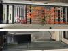
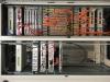
The first photo is showing the timing rack before the changes, the second one after the changes, the top parts of two racks are now used (the bottom part with orange and yellow fibers are the MuxDemux).
The attached schematic (non-image pdf file) is describing the logic of the new system that is the following.
The timing starts by the IRIG-B signal (that is encoding the GPS time) provided by a GPS receiver located on the top left rack.
Since we are still using the old GPS receiver that from time to time are sending twice the same GPS time, the IRIG-B signal is going first trough the DAQbox 57 (slaved on this IRIG-B) which is providing a proper increasing GPS timing and output the signal as a new (or corrected) IRIG-B on a special mezzanine. This is IRIG_B that is then used everywhere (side remark: a Timing Distribution Box (TDBox) v1 is also used to convert the single ended signal of the GPS receiver to LVDS needed by the DAQbox). This will have to be replaced in a couple of months when the new GPS receiver will be available and fully tested.
The new IRIG-B signal is then send to the usual block of TDBox that are providing the appropriate 16 us delays for the central building to compensate for the propagation along the arms.
The IRIG-B signal from the GPS receiver is also sent via a coax cable to the "mezzanine timing" located on slot 3 of the DAQbox 59 to slave a 100 MHz clock. This 100 MHz clock is then send to the TDBox v2 that is providing multiple outputs to distributed via LVDS signals the 100 MHz clock (together with the IRIG-B) to the DAQboxes used to demodulate the LNFS, SIB2, SPRB, SDB2 and squeezer signals. TDBoxes v2 have also been installed in the laser lab and detection lab electronic rooms. The "mezzanine timing" is also providing a synchronous 10 MHz clock that is distributed by the old timing distribution system, and are especially used by SNEB and SWEB.
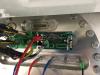
On all minitowers electric feedtrough, the small board that was doing the interface was replace by new ones that includes components to boost the signal level to compensate for the losses in the in vacuum "white" cables in order to have cleaner 100 MHz signals arriving on the suspended in vacuum benches (see the third photo for SNEB as an example). The common mode of the LVDS signal has been increased to 2.5 V on that board to have enough common mode when arriving on the DAQbox inside the bench.
The free running atomic 10 MHz clock has been moved in the timing racks. Its output is monitored by the DAQbox 59, and is also send to the laser lab electronic room to be monitored as previously and measure timing distribution noise. Similarly, the 100 MHz clock of the TDBx v2 located in the laser lab electronic room is sent back to the DAQbox 59 in the DAQ room. Others monitoring signals are also acquired by the DAQbox 59.
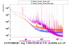
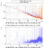
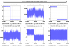
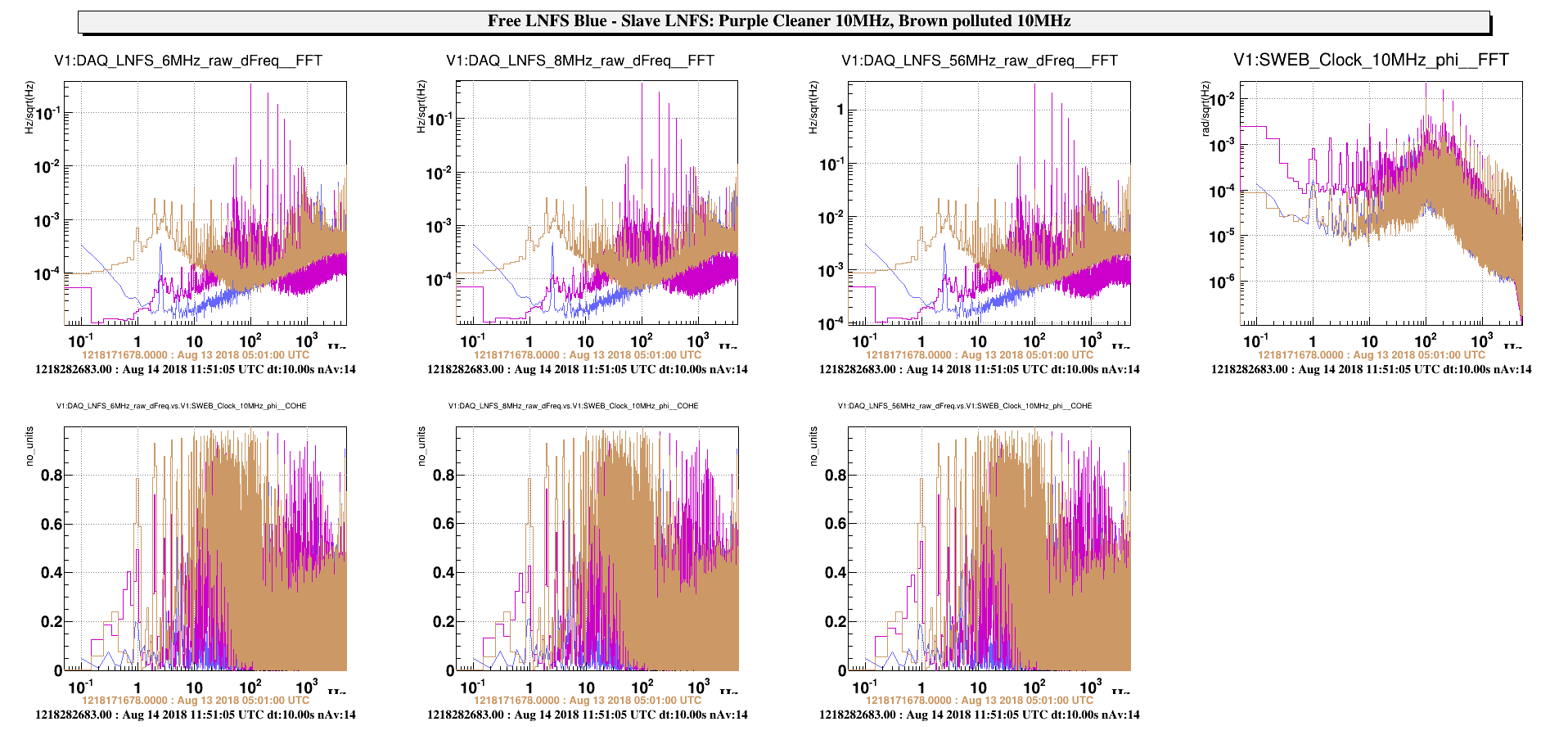
The first plot is comparing the measured noise of the 10 MHz free atomic clock, which includes the demodulation noise, before (purple line) and after the change (blue line when measured in the DAQ room by the DAQbox 59 and orange line when measured in the laser lab electronic room after a 50 m coax cable propagation). The noise floor is reduced up to several hundred Hz as well as the various lines.
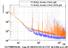
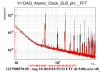
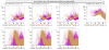
The second plot is showing the spectrums and coherence of the 100 MHz clock, measured in the DAQ room (orange line) and after a round trip (50 m LVDS propagation + TDBox v2 + 50 m coax cable) to the laser lab electronic room (orange). The difference is a measurement of the timing distribution noise by the cables and the TDBox v2.