This morning we centered the beams on the photodiodes and quadrants of the SDB2 bench. The beams have also been centered on the B1p and B1 cameras.
The table below gives the number of steps which have been performed on each picomotors used to center the photodiodes.
| Degree of freedom | Number of steps |
| B1p M4 H | -1500 |
| B1p M4 V | +2000 |
| B1p PBS H | -3800 |
| B1p PBS V | +1000 |
| B1p M1 H | +3550 |
| B1p M1 V | +3600 |
| B1p M2 H | -1000 |
| B1p M2 V | +2100 |
| B1p M5 H | -7000 |
| B1p M5 V | -1000 |
| B1p M6 H | +6000 |
| B1p M6 V | +3000 |
| B5_M1_H | -300 |
| B5_M2_V | -200 |
| B1s1 M1 H | +3680 |
| B1s1 M1 V | +50 |
| B1s1 PBS H | +500 |
| B1s1 PBS V | +2500 |
| B1s2 M1 H | -1000 |
| B1s2 PBS H | -250 |
| B1s2 PBS V | -500 |
| B1 M1 H | +1500 |
| B1 M1 V | +4500 |
| B1 M2 H | +4000 |
| B1 M2 V | +3000 |
| B1 M3 H | -7000 |
| B1 M3 V | -5000 |
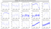
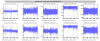
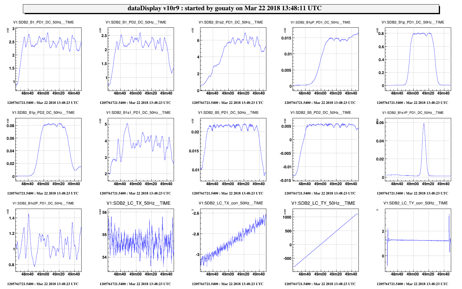
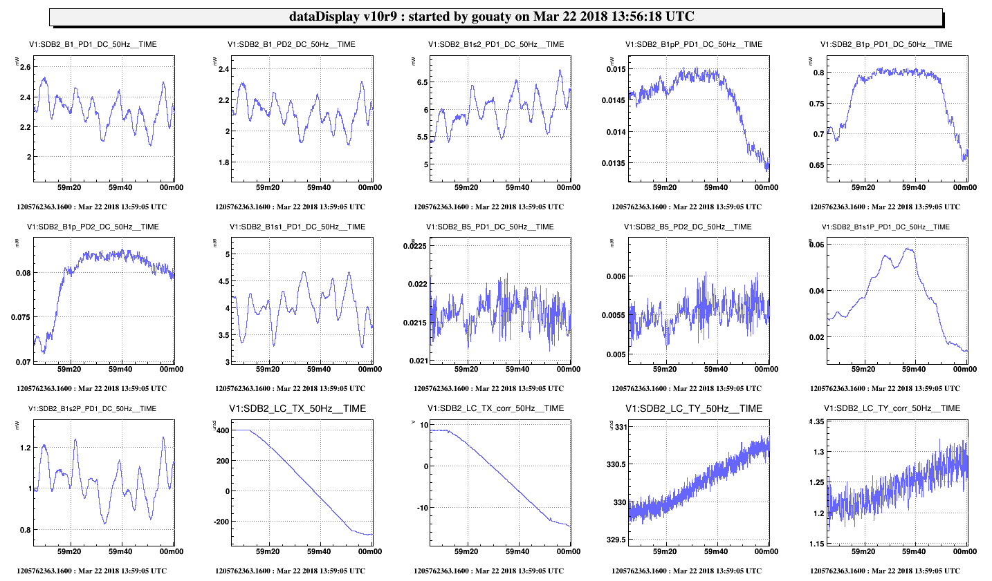
A scan of the angular positions of the bench was then performed in order to check the quality of the photodiode centering: see Fig.1 for TY scan and Fig.2 for TX scan. The nominal set points are TX=+55 and TY=+330 which correspond roughly to the middle of the plateau on all longitudinal photodiodes. To be noted that the B1s1P photodiode does not have a plateau which means that this photodiode can easily be miscentered.
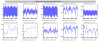
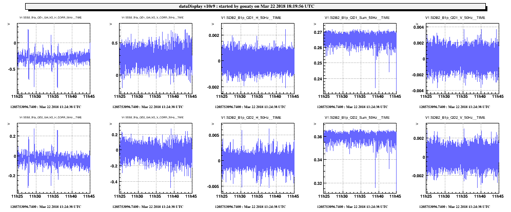
The quadrants have been aligned in such a way that the automatic centering with galvos could be closed with low corrections (see Fig.3 for B1p and Fig.4 for B5).
Note that despite the correction of the offsets performed last tuesday (40835), large residual offsets were found again on the B5 quadrants as shown below:
B5 QD1 H: 0.00061 V: 0.0078 Sum: 0.0078
B5 QD2 H: 0.00048 V: -0.1629 Sum: -0.00097
Offsets were updated in the configuration file before aligning the quadrants.
