The goal of the shift was to adjust the OMC mode matching. First we worked in Low Noise 3 aligned in order to find the position of the SDB1 bench that would optimize the mode matching. Then we worked in single bounce in order to reset the nominal position of the SDB1 bench that we had during O4, while adjusting the position of the meniscus lens to preserve the mode matching tuning.
When the shift started the ITF was still trying to lock. State Low Noise 3 aligned reached at 8h14 utc.
The initial position of SDB1 is SDB1_LC_Z = 1204 um and Sa_OB_F0_X = -400.
At 8h36 utc we start to scan the SDB1 bench going from F0_X = -400 to -1400 um, in 1000 s.
At 9h07 utc we start to scan from F0_X = -1400 to -2400 um in 1000 s.
At 9h28 utc we start to scan from F0_X = -2400 to 600 in 3000 s.
At 10h30 utc we start to scan from F0_X =600 to 1600 in 1000 s.
At 10h54 utc we start to scan from F0_X = 1600 to 2600 in 1000 s.
On Fig.1 and Fig.2 we see that the optimum of optical gain was reached around 10h00 utc when the bench position was Sa_OB_F0_X = -500 um.
We then unlocked the interferometer manually and started to work with the NI single bounce.
We displace the SDB1 bench to Sa_OB_F0_X = -500 um, where we found the best mode matching in LN3 aligned.
Then we adjusted manually the TX angular position of the bench to TX=225 urad in order to center the B1p beam on the camera. Then we lowered the threshold on B5_QD2_sum in order to be able to engage the drift control.
We lock the OMC at 12h18 utc.
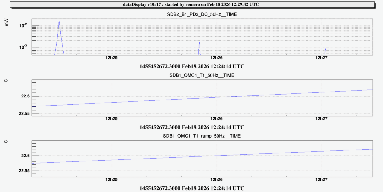
We start the OMC scan at 12h22m40 utc (See Fig.3). We measured 15 uW on the TEM00, 1.6 uW on the first order mode (10% of misalignment) and 0.8 uW on the second order mode (5% of mode mismatch). Given the relatively large misalignment we decide to relock the OMC and improve the alignment.
OMC locked again at 12h37 utc (see Fig.4). We tried to maximize the power on the TEM00 by adding offsets in the B5 QD2 H (-200) and V (+100) signals.
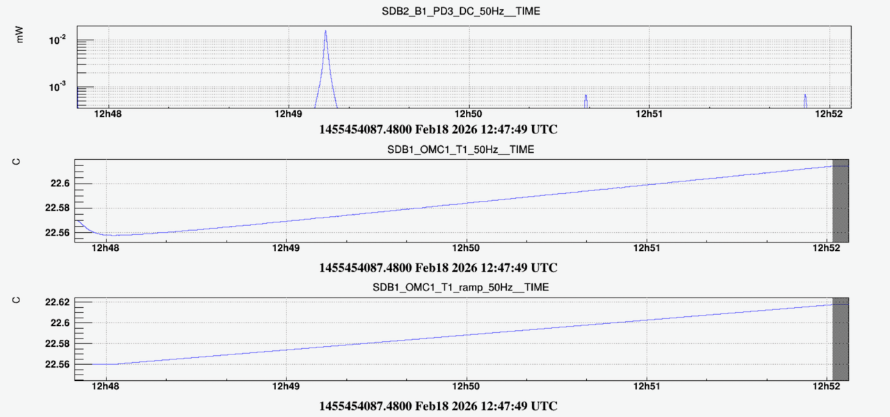
New OMC scan at 12h48 utc (Fig.5). We measure 16 uW on the TEM00, 0.65 uW on the first order mode (4% of misalignment), and 0.68 uW on the second order mode (4.2% of mode mismatch).
We restore the SDB1 bench position that we had during the O4 run (F0_X = 2600 um).
Since the optimal position of SDB1 that maximizes the mode matching in LN3 is -500 um, this means that the meniscus lens should be displaced by 3100 um. From a measurement performed in Feb 2024 ( https://logbook.virgo-gw.eu/virgo/?r=63269 ), we estimated that 4 mm correspond to about 113500 steps. Therefore we should displace the meniscus lens by about 88000 steps, and we should perform positive steps which are equivalent to a negative displacement of the bench.
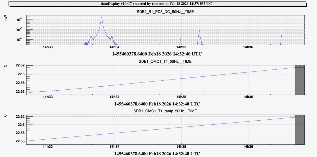
After displacing the meniscus lens by only 5000 steps and upon Michal's suggestion, we locked the OMC again at 14h21m40 utc and adjusted finaly the alignment with the B5 QD2 offsets. Then we performed a new OMC scan at 14h32 utc (see Fig.6): we measured a TEM00 of 17 uW, a first order mode of 0.9 uW (5.3% of misalignment) and a second order mode of 0.26 uW (mode mismatch of 1.5%).
We displaced the meniscus lens by a total of +88000 steps (by +2500 steps at a time). In order to keep the bench balanced we also moved the BENCH_TX counter-weight by +117500 steps.
We then lock the OMC at 15h24m40 utc. We try to adjust the B5 QD2 offset to optimize the OMC alignment (H -150 and V +50).
We start a new OMC scan at 15h37m30 utc (Fig.7): we find 16.5 uW on the TEM00, 0.75 uW on the first order mode (4.5% of misalignment), and 0.55 uW on the second order mode (3.3%) of mode mismatch. As the mode mismatch is still a bit smaller than the one we found when the bench was at F0_X = -500 um, we decide to move the meniscus lens a bit further.
We displace the meniscus lens by another +15000 steps (by +2500 steps at a time), compensated with +17500 steps on BENCH_TX.
We relock the OMC at 16h07 utc. We try to adjust the OMC alignment with B5_QD2 offsets (H:-175, V:+100).
Started a new OMC scan at 16h18m53 utc (Fig.8): we find 16.5 uW on the TEM00, 0.86 uW on the first order mode (5.2% of misalignment), and 0.6 uW on the second order mode (3.6% of mode mismatch).
We displace the meniscus lens by another +17500 steps (by +2500 steps at a time), compensated with +22500 steps on BENCH_TX.
We relock the OMC at 16h44m30 utc. We try to adjust the OMC alignment with B5_QD2 offsets (H:-200, V:+100).
Started a new OMC scan at 16h58m43 utc (Fig.9): we find 16.4 uW on the TEM00, 0.83 uW on the first order mode (5% of misalignment), and 0.8 uW on the second order mode (4.9% of mode mismatch). The mode mismatch is now a bit higher than what we were aiming at.
We undo -8750 steps on the meniscus lens, compensated by -10000 steps on BENCH_TX.
We perform another OMC scan at 17h18m09 utc (Fig.10): we find 16.3 uW on the TEM00, 0.83 uW on the first order mode (5% of misalignment), and 0.74 uW on the second order mode (4.5% of mode mismatch).
We consider that the obtained mode mismatch of 4.5% is sufficiently closed from our target (4.2% with some error bar). Therefore we stop the tuning here. In total we performed 111750 steps with the meniscus lens, and 147500 steps with the motorized counter-weight.
To be noted that we have changed the threshold on B5_QD2_sum in order to be able to engage the B5 drift control on the single bounce beam, as shown below :
ACL_RELAY_CH B5_QD2_safe "" LC_LOOP_FREQ 20 0.0 -2 "B5_QD2_sum" 1.6 1.4 ">=" # 2.5 1.8
.png)
.png)
.png)
.png)
.png)
.png)
.png)
.png)
.png)
.png)
.png)
.png)
.png)
.png)
.png)
.png)