Today we continued to investigate the IPATSiA effects on the ITF through the PA injected on the WI HR surface mirror. The last IPATSiA shift was reported here #68304.
In the morning, at 9 UTC we switched on the chiller, the laser and started shining the mirror with 32 mW of CO2 power at 10:35 UTC when the ITF was stabilized at LN2.
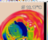
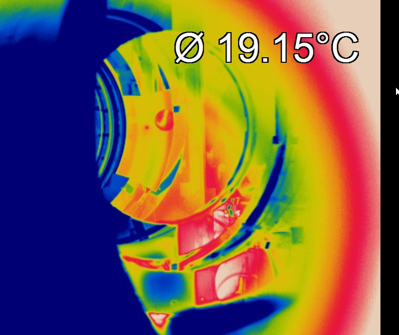
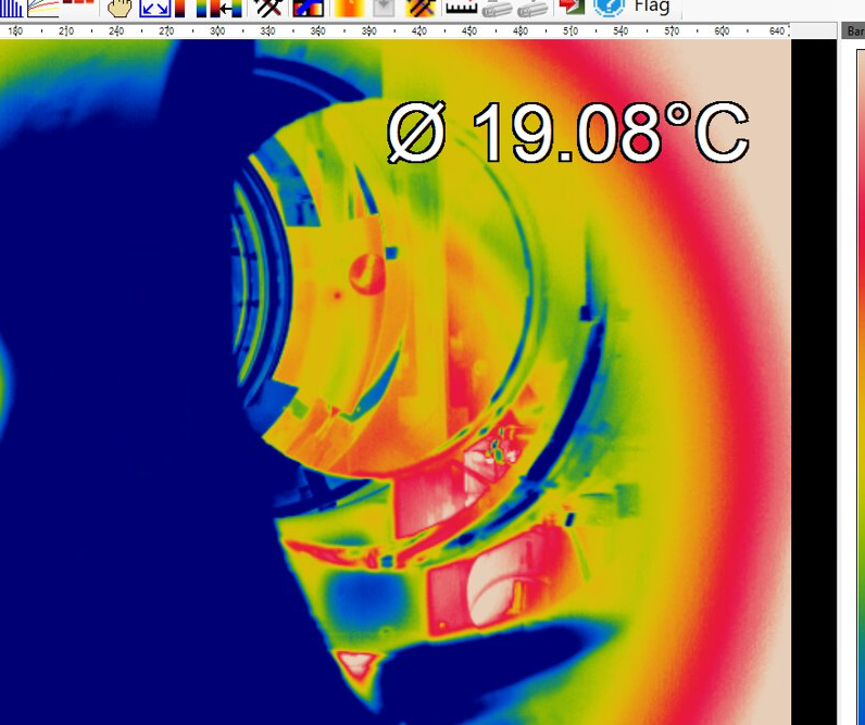
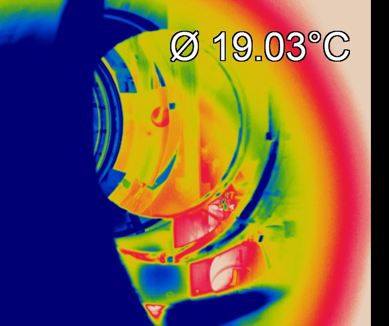
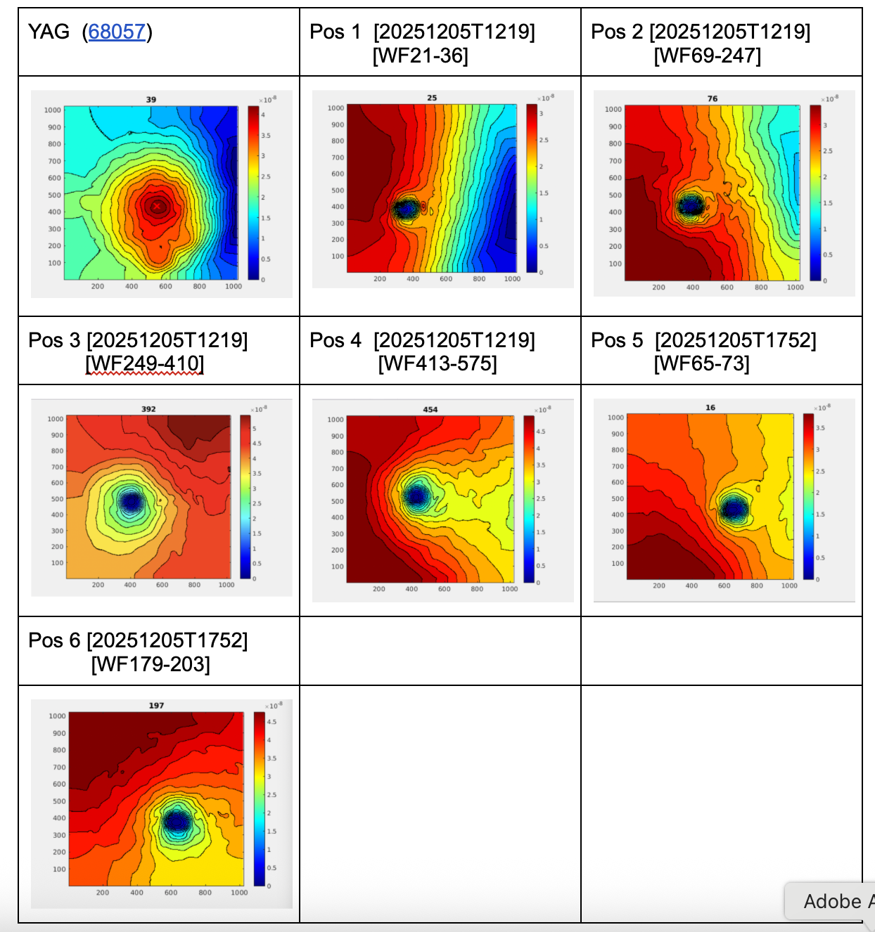
In Fig.1 we can see the new position of the PA (POS 1). To be noted that this position is different from all positions from the other shifts. We moved in the horizontal direction to the left and the idea is to scan some points in the vertical direction. Also to be noted that the thermocamera used is a different one w.r.t the other shifts. Since the thermocamera used before had an issue and we had to restart it every few seconds, we installed a new one, but this time facing the HR mirror with the same height and therefore there is no vertical angle of view. Moreover, this camera is not flipped upside down as the other one (this was necessary to install it in the setup), so to understand the relative position of the PA it is necessary to keep this in mind (see Fig. 2: here we have the old thermocamera image of the POS1, i.e., the same position of the new thermocamera shown in Fig. 1).
When we started shining the mirror a big oscillation in all signals of the ITF (PR, BS, arms signals, ect) unlocked the ITF. After locking again in LN2, we tried again (started shining the mirror at 11:27 UTC) but we had the same effect as before so we decided to stop shining the mirror (11:32:37 UTC) and change position (+10k steps of the picomotor, corresponding roughly to 8 mm dwon w.r.t the previous position).
So, here below a list of the positions and corresponding UTC time. Each position is 8 mm down w.r.t the previous one:
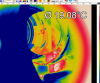
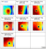
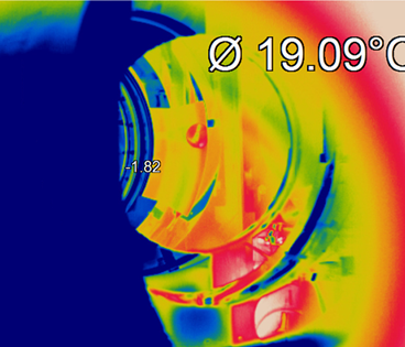
- At 11.45 UTC we started shining the mirror in POS2 (Fig. 3);
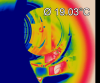
- At 12:52 UTC we moved to POS3 (Fig. 4);
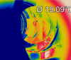
- At 13:53 UTC we moved to POS4 (Fig. 5);
Then, at 14.55 UTC we moved the PA horizontally in the mirror towards the right direction - POS5 (Fig. 6). However the ITF unlocked and we stopped shinning the mirror at 15 UTC. After some atempts to shine the mirror with the PA, the ITF did not manage to remain locked in LN2 in this position. At 17.36 UTC we moved again the PA upwards (8mm up) to try in this new position. The ITF relocked in LN2 and we tried to shine the mirror at 17.59 UTC but the ITF unlocked again at 18.09.15 and we stopped the shift here.
Around 18.15 we switched off the CO2 laser and the chiller.
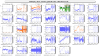
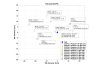
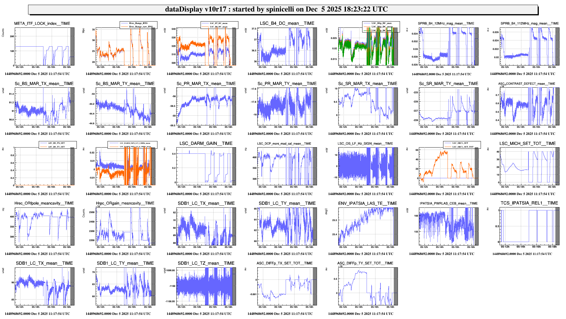
On Fig. 7 we show a summary of the main signals during the whole shift.

