Today the noisy photodiode on B1_PD2 was replaced by a spare photodiode.
The activity went on following the procedure described in attachment.
The venting started slightly before 7h30 utc. The SDB2 bench was opened between 9h00 and 9h30 utc.
The Power Unit 09 output was switched off at 09h35m44 UTC in order to allow to safely unplug the photodiode.
The airbox 23 was removed from the SDB2 bench (it was the former B1_PD2 photodiode), and replaced by the airbox 22.
Both airboxes were weighted, and the difference of weight was of the order of 0.3 g, therefore negligible.
After the replacement of the photodiode, the PowerUnit 09 output was enabled back at 10h13 utc. Then the SDB2 DAQ boxes were reconfigured.
Taking 3 min of data from 10h20 utc with Vbias ON and B1 shutter closed to have a reference for the dark noise of the "cold" photodiode.
With the bench released and angularly controled in air we could check that the single bounce beam was reaching the two B1 photodiodes with almost equal powers.
Then the SDB2 minitower was closed and the evacuation started around 11h40 utc.
With the vacuum restored, Henk Jan restored the position of the bench (https://logbook.virgo-gw.eu/virgo/?r=67937) and closed the control loops.
We then checked the alignment of the B1_PD2 photodiode using the NI single bounce beam, and adjusting the OMC temperature close to the resonance of a SB TEM00 located at about 22.511 deg. We did not succeed in locking the OMC on this mode, probably because of its too small power (only ~0.1 uW on B1_PD3), but with the OMC temperature roughly stabilized on the mode, we were able to check the alignment of the B1_PD2 photodiode by scanning the picomotor B1_M2 and checking the power variation onb B1_PD2 compared to B1_PD1.
Alignment of SDB2_B1_PD2 photodiode with B1_M2_H +4000 steps and B1_M2_V -500 steps.
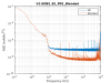
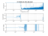
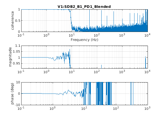
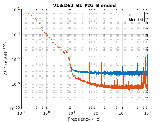
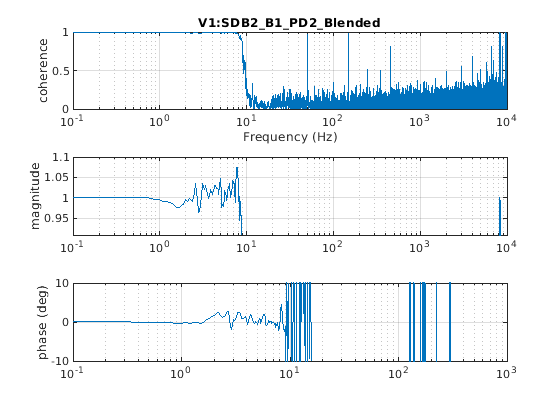
We collected some data from 14h18m20 utc to 14h22m20 utc, with the OMC close to the resonance of this SB TEM00 mode (with 0.06 mW on B1_DC). We used these data to check the blending of the photodiodes (see Fig.1 and 2 for B1_PD1 and Fig.3 and 4 for B1_PD2). The overlap between the blended signal and the DC signal seems to be reasonable and the TF are qualitatively quite similar for B1_PD1 and B1_PD2, therefore we decided to not update the blending filters of B1_PD2. A more precise check will be performed once we have new data in DC readout.
Then the recovery of the ITF started. During this phase we had to repeatedly update the offset of B1_PD3, probably because of the on-going thermal transient.


.png)
.png)
.png)
.png)