Yesterday morning, we performed some preliminary tests in preparation for the CO2 noise injection.
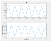
As the first step, we injected a triangular wave with long period (20 s) to look at the DC gain of the conversion Piezo voltage/laser power, and to find a suitable linear response region
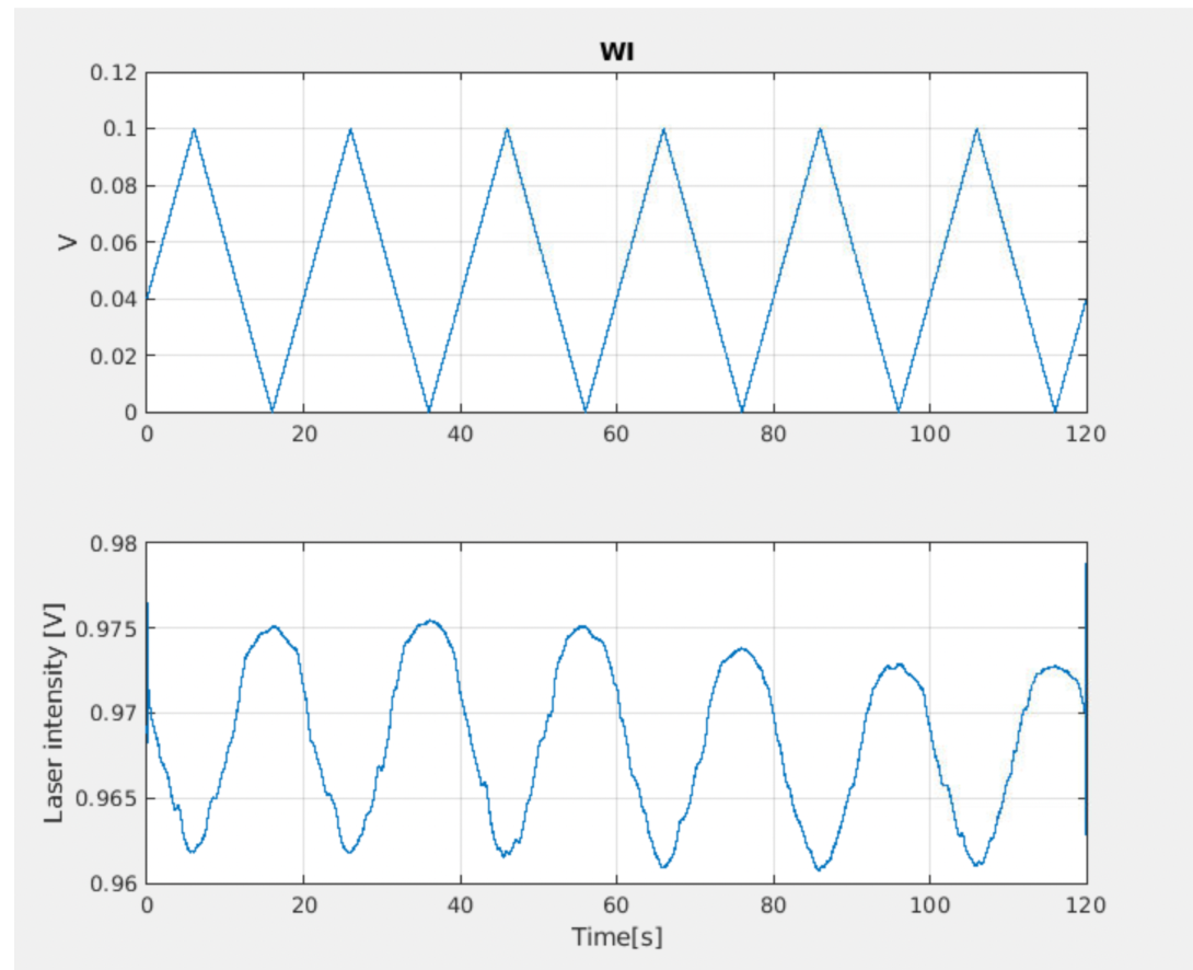
WI
Amplitude : 0.1 V
Period: 20 s
We injected the trangular signal in the time interval: 09.34.50 UTC-09.36.50 UTC (see fig.1)
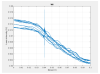
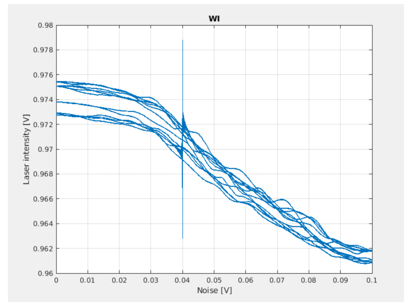
The laser power vs noise signal is shown in fig. 2.
We did a similar injection on NI laser, but nothing was visible in the photodiode (ISSIN) or in the beam sampler (PRWLAS). However, after a series of checks done directly in tcs room by Beatrice, such as:
-check the status of the CO2 laser piezos
-check the cabling between the Piezo Driver and the CO2 benches,
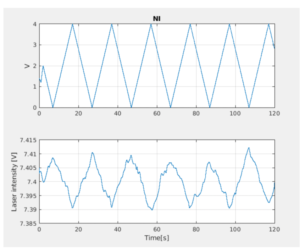
no malfunctioning have been identified. Finally, we have found that the piezo effective gain is much lower than for WI laser. Thus, by injecting larger signal we were able to see the effect also on the NI laser.
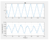
NI
Amplitude : 4 V
Period: 20 s
We injected the triangular signal in the time range: 10.33.54 UTC-10.35.54 UTC (see fig.3)
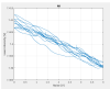
The laser power vs noise signal is shown in fig. 4.
To conclude, we need to proceed with a calibration of the piezo, both in amplitude and in frequency:
-apply the sinusoidal signal to the piezo at fixed amplitude for different frequencies
-apply sinusoidal signal to the piezo at fixed frequency for different amplitudes and measure corresponding signal on the photodiode.