This morning the exploration of the working point went on in a new direction: changing the vertical position of the ITMs. This was done in order to substitute another interesting dof: the vertical shift of the beam, difficult to do from IJN side. Unfortunately we were able to do only 1.7 mm, because the saturation of the actuators was reached.
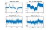
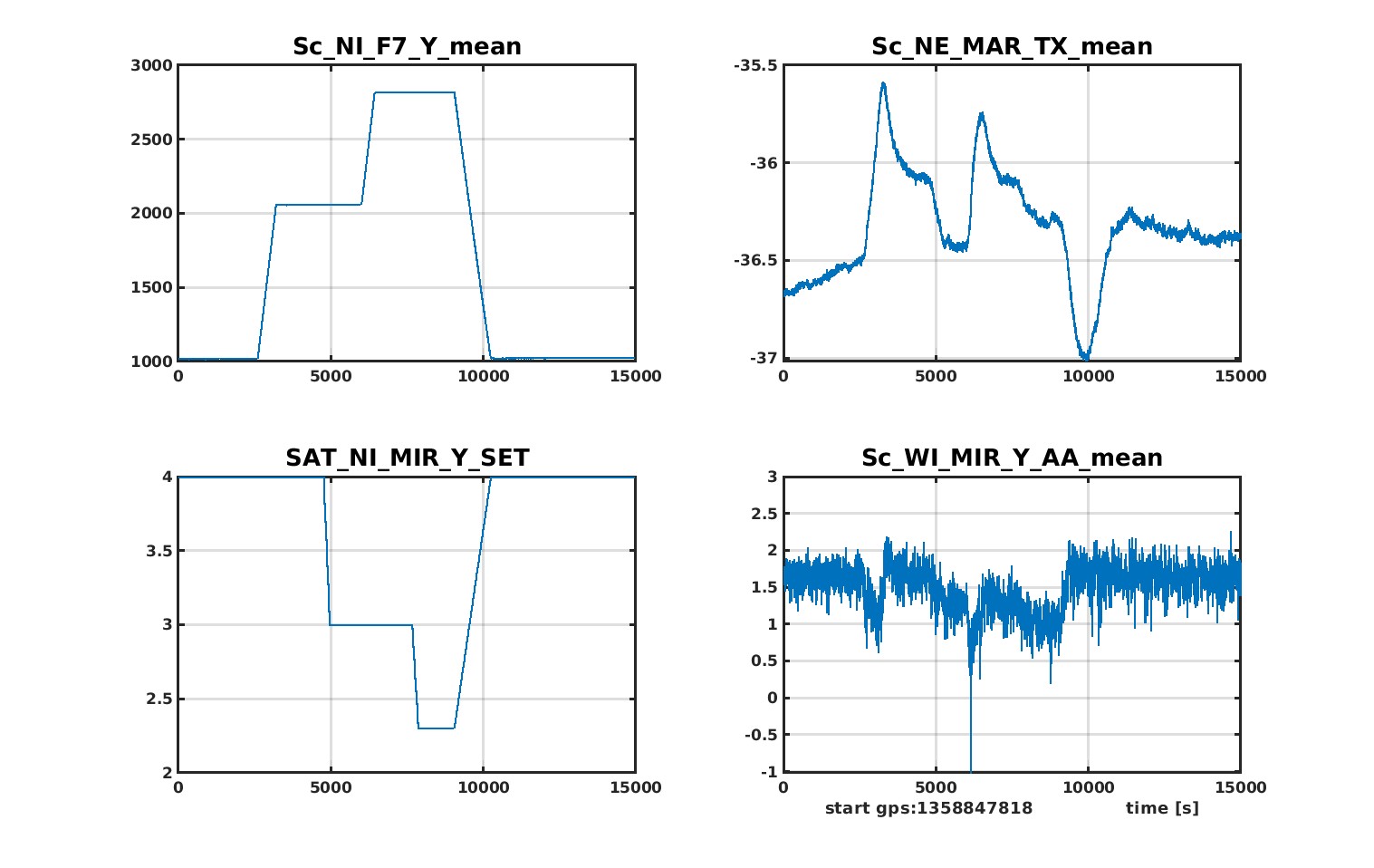
Fig 1 shows the sequence of the actions:
1) 1 mm vertical displacement of NI (and WI, not shown in the plot). The alignment on NE_TX, based on NI dither signal, followed the shift, keeping the axis in the same position. The witness shown in the plot is WI vertical centering, out of loop dither signal. Please don't look at the transient during the ramp: many alignment loops are to slow to guarantee the conservation of the alignment while things are moving. Only the steady state after the step is relevant.
2) An equivalent step has been done bakwards on the dither loop, in order to put back NE_TX and the optical axis in the previous absolute position (closer to the center on NI by 1mm). NE optical lever says that the direction was right, and also the intercalibration not so bad. WI dither says that a motion of the axis was visible also there, but the measured value was less than one half. This is in ageement with the fact that the starting position on WI was apparently closer to the center by a factor of 2 or more. The signals should be recalibrated accordingly.
3) Second step of vertical shift (0.7 mm).
4) Second step of axis adjustment
5) The step back to put everything in the standard working point was done all in one: -1.7 mm in ITM position and +1.7 mm in axis position on ITM, with the same ramp at the same time. This action consists in moving only the ITMs (apart from the undesirable transient). Beam direction and axis direction should stay where they are, apart from some natural drift.
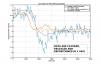
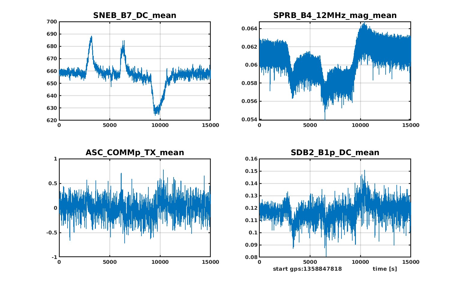
We explored the effect on the ITF looking at several signals: the most relevant was found in the sideband power (fig 2). Power in the cavity and dark fringe were not affected in a macroscopic way. Not yet so clear in fig 2, but present, was also a drift in COMMp_TX signal.
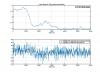
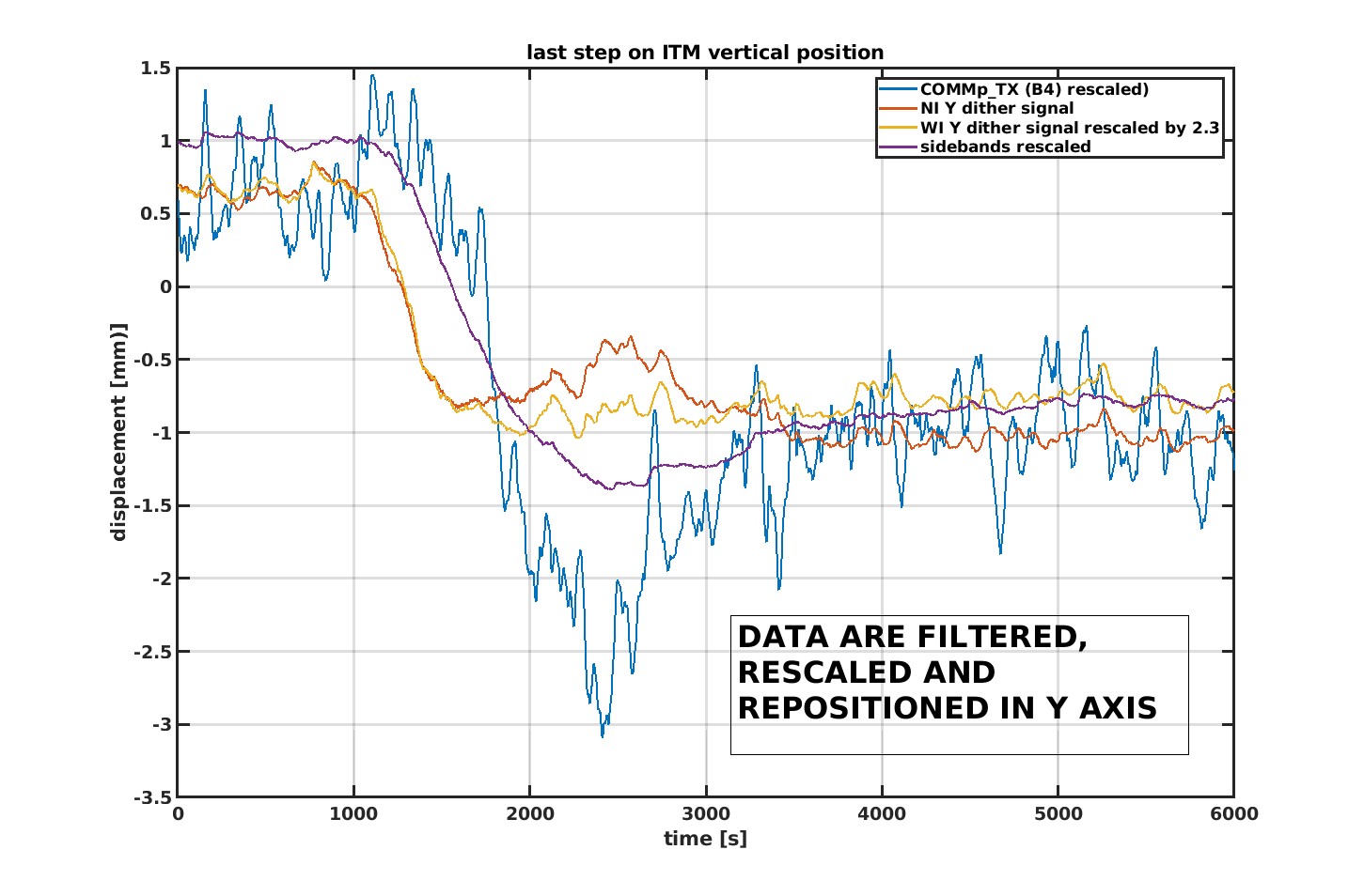
In order to appreciate better the variatons of those two signals with respect to the variation of ITMs vertical position, some filtering and rescaling have been applied and shown in fig 3. Only the last step has been taken into account. Here, the variation of B4_12_MHz_mag and B4_QD_6_MHz_V are compared to the shift of the axis on the ITMs. Usually this kind of variations are attributed to a change of relative alignment between beam and arm axis. In principle this is something we were trying to avoid, so there is some doubt about this explanation. But a residual misalignment was there for sure, because the intercalibration between the ITM shift and the dither readout cannot be perfect. It is difficult to evaluate that, even if the check done on the optical levers says that the error cannot be huge. Expressing the misalignment in mm of mismatch at the ITMs, I would say a few hundreds of microns and no more.
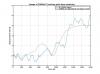
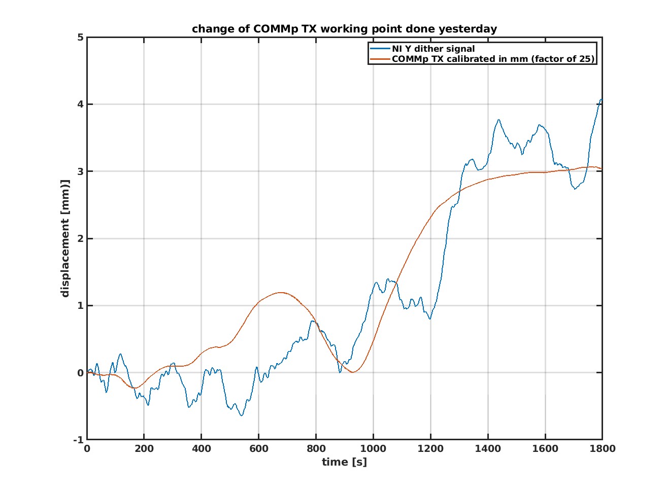
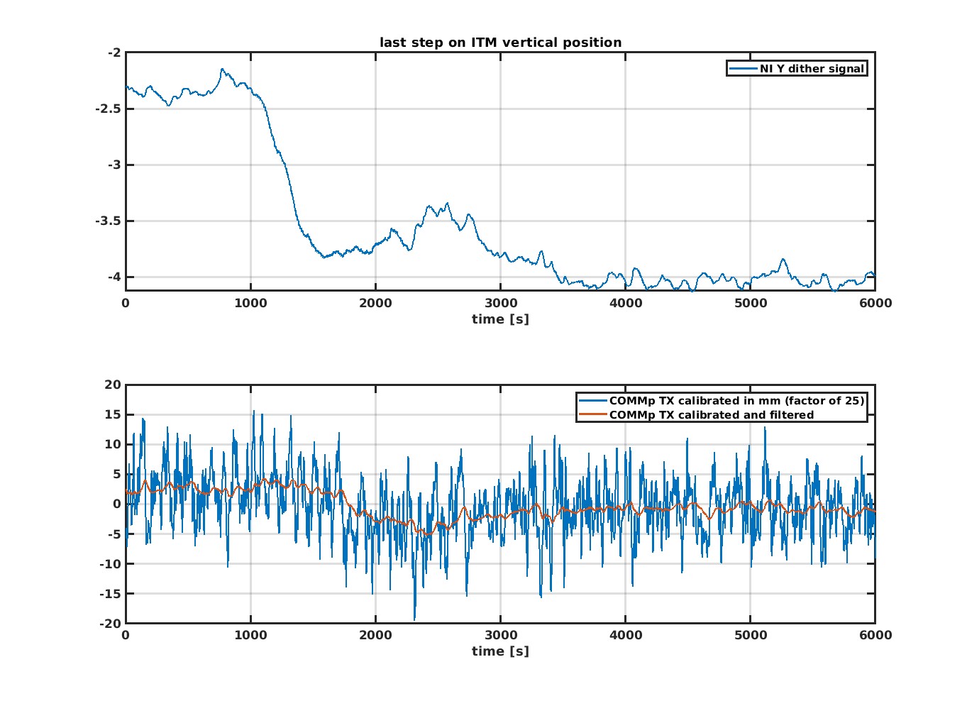
In order to understand if the variation observed on the quadrant is compatible with a misalignment, a calibration of the quadrant is needed. An attempt has been done by using the misalignment performed yesterday during an attempt to close COMMp on the center of the dithers. Fig 4 shows the result, which is a factor of 25 for the conversion from COMMp_TX to mm on NI Y dither.
The same factor has been used to convert the data collected today (fig 5). The measured step on the quadrant is a few mm, let's say a factor of 10 larger than the supposed one. So I would exclude that the variation was due to some undesired rotation of the test masses. Eventually it could be some 'internal' misalignment: the beam can be deflected by some lens which is changing positon with respect to it.
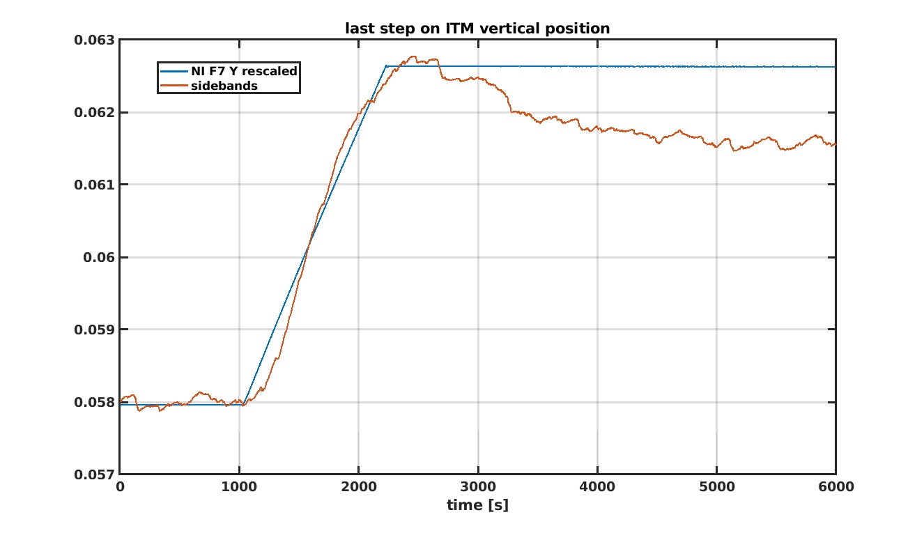
It is interesting to see how well a variation of sideband power is correlated to the shift of the ITMs (fig 6). Let's remark that the ITMs where shifted using the controlled stage of the suspension (top stage), so also the CPs where shifted together with the TMs.
