This morning we worked on the OMC mode matching tuning, and performed some alignment checks on SPRB and SIB2.
First Gianmatteo put the ITF in NI single bounce in order to perform the activities on SPRB and OMC mode matching.
We started by recentering the B4 beam on the camera (it was slightly off centered) at the beginning of the shift. SPRB new angular angular setpoints: TX=156, TY=-663
We opened the OMC shutter using DET_MAIN, then we tested the shutter closing and we saw that it was not working: Michal found a bug in the graph of the node, as two paths are possible to go from "SHUTTER CLOSED" to "SHUTTER OPEN". The problem was linked to the fact that metatron was chosing a different path than the one it used to. Michal fixed this issue by increasing the length of the path that we do not want metatron to select. Then the OMC shutter closing worked successfully.
We performed a first scan of the OMC at 07h08m40 utc to check the initial status of alignment: TEM00 peak 0.04mW, order 1 peak at 0.02 mW. Thus the OMC was strongly misaligned.
OMC locked at 07h41m20 utc, and realigned using the picomotors on SDB1.
Another OMC scan at 07h55m40 utc to check the initial status of mode mismatch: TEM00 0.050 mW, order 1: 0.0013 mW (mostly horizontal) > 2.6% misalignment defect, order 2: 0.008 mW > 16% mode mismatch.
We started the mode matching tuning by moving the SDB1 bench along the longitudinal axis by acting on the suspension top stage (F0_X). Our starting point corresponds to: Sa_OB_F0_X = -2200 and SDB1_LC_Z = -64 um. Bringing the suspension top stage at 0 (F0_X = 0) we noticed that the mode matching was improving (the transmission through the OMC was increasing as well as the normalized signal B1_PD3_norm_B1s).
Then we moved the meniscus lens SDB1_L1_Z in the negative direction (which corresponds to positive direction for the bench). In parallel we reajusted the balancing of the bench by acting on the motorized counter-weight (BENCH_TX). Below are the details of the steps we performed:
| SDB1_L1_Z | -60000 | -80000 | -70000 | -80000 | TOTAL: -290000 steps |
| BENCH_TX (counter weight) | -150000 | -140000 | -130000 | -140000 | TOTAL: -560000 steps |
We realigned the OMC after the first -140000 steps and after the -290000 steps. Each time we noticed a clear improvement of the OMC mode matching.
Performing -60000 steps with the lens seemed to be equivalent to +500 um with the suspension for the mode matching. Thus we estimated that the meniscus lens was displaced by ~2.5 mm. Concerning the motorized counter-weight, it is likely that we have used most of its available range, thus we preferred to stop moving the lens farther to not risk blocking the counter-weight if we reach the end of range.
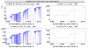
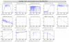
We continued improving the mode matching by moving the suspension top stage towards positive X values. Fig.1 shows the overall trend of the OMC transmission during the tuning of the mode matching (the meniscus lens was moved between 8h30 and 9h30 utc).
Sa_OB_F0_X at +2500:
carrier TEM00 reaching about 0.062 mW.
OMC scan (with rising up temperature) started at 10h05m20 utc:
Order 1: small
Order 2: 0.0011 mW > 1.8% mode mismatch
New scan (with decreasing temperature) at 10h14m16 utc:
order 1: 0.00025 mW > 0.4% of misalignment defect
order 2: 0.0012 mW > 1.9% mode mismatch
Sa_OB_F0_X at +4500:
Scan of the OMC at 11h14m00 utc:
order 1: 0.00042 mW > 0.7% misalignment
order 2: 0.0003 mW > 0.5% mode mismatch
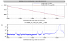
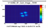
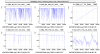
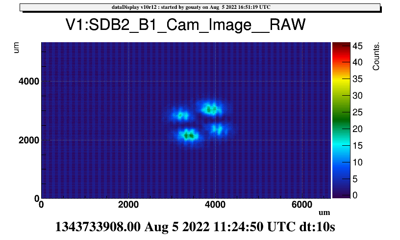
Scan decreasing at 11h21m30 utc (integration time of B1 camera increased at maximum) - see Fig.2:
order 2: 0.0003 mW (the mode has a nice shape of 4 leaf clover - see Fig.3).
order 1: 0.00046 mW
As the suspension was close to its end of range (+5000), and the bench LVDT were quite off-centered (SDB1_LC_Z = 5500um), this bench position did not seem optimal for the local control, thus we decided to come back to the suspension position Sa_OB_F0_X at +2600 um. We keep this as nominal setpoint for the time being.
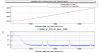
After realigning the OMC we performed a final scan at 11h55m00 utc (see Figure 4):
Order 1: 0.0007 mW
Order 2: 0.0009 mW > 1.5% mode mismatch
Conclusions on the OMC mode matching tuning: We demonstrated that a mode mismatch of 0.5% can be reached. However, in order to limit the off-centering of the suspension and bench LVDT we decided to stay at a working point where the mode mismatch should be at the level of 1.5-2%. In the future we would like to move further the menicus lens is that is possible.
After the OMC mode matching activity, we closed the OMC shutter and updated the SDB1 angular setpoint in the config file.
Then Gianmatteo aligned the PR mirror and we could check the alignment of the photodiodes on SIB2 bench:
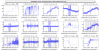
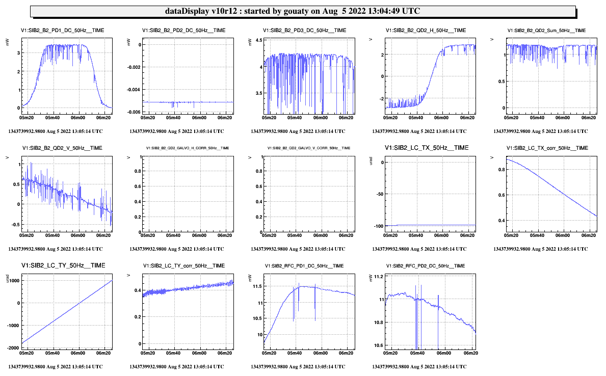
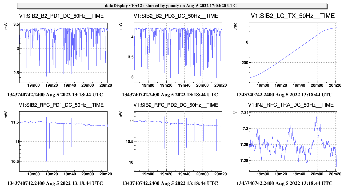
To this purpose we scanned the SIB2 bench in TY: Fig.5 and in TX: Fig.6.
For the current bench angular setpoints (TX = -100 and TY = -325 urad) the beam seems well centered inside the B2 photodiodes (we are close to the center of the plateau visible in the TY, and the TX scan does not change the power on these photodiodes). For the RFC photodiodes, we observe a slow trend as we displace the bench. It does not look like the beam going out from the photodiode (no sudden drop). I wonder if it could be related to the beam size and shape (mode of order 1), which could be slightly clipped, or some junk light (reflection on AR coating for PD2), or maybe a polarization effect.
We checked that the galvo loops of B2_QD2 could be closed with the DC centering. Switched back to 2f centering after the test.
At the end of the shift, we updated the current limit threshold of the B4 photodiodes to 90 instead of 80 mA, to try to solve the issue mentioned yesterday: https://logbook.virgo-gw.eu/virgo/?r=56646 . SPRB configuration reloaded at 14h05m38 utc.