We did some improvements on the WE pcal process
- We measured the offsets of the channels Tx_PD1_DC, TX_PD1_Audio, and Tx_PD2_DC, and wrote it on the "SWEB_dbox_rack" config file.
| channels | Tx_PD1_DC | Tx_PD1_Audio | Tx_PD2_DC |
| offset (W) | -5.194e-3 | +4.193e-3 | -9.195e-3 |
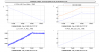
- On the laser controller, we compute the gain and offset between the power required and the control tension of the laser. offset = 0.18 V; gain = 0.93 V/W
To do so, we set the tension command to 0.5V, 1.0V, 1.5V, and 2.0V and measured the power of the laser on the channel Tx_PD1_DC, which measure the power of the laser reflected by the end-mirror. And made a linear regression between the command and the power measured. Therefore, the power required is supposed to be the power reflected by the end mirror.
- Alain improved the control loop between the laser and Tx_PD1_DC. By reducing some delays and improving the server configuration.
He also made a new boost filter. with a gain of 1 at 5kHz and order 2 poles and zeros
| Poles frequencies (Hz) | 0.005 | 400 | 5000 |
| Zeroes frequencies(Hz) | 0.5 | 440 | 8000 |
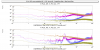
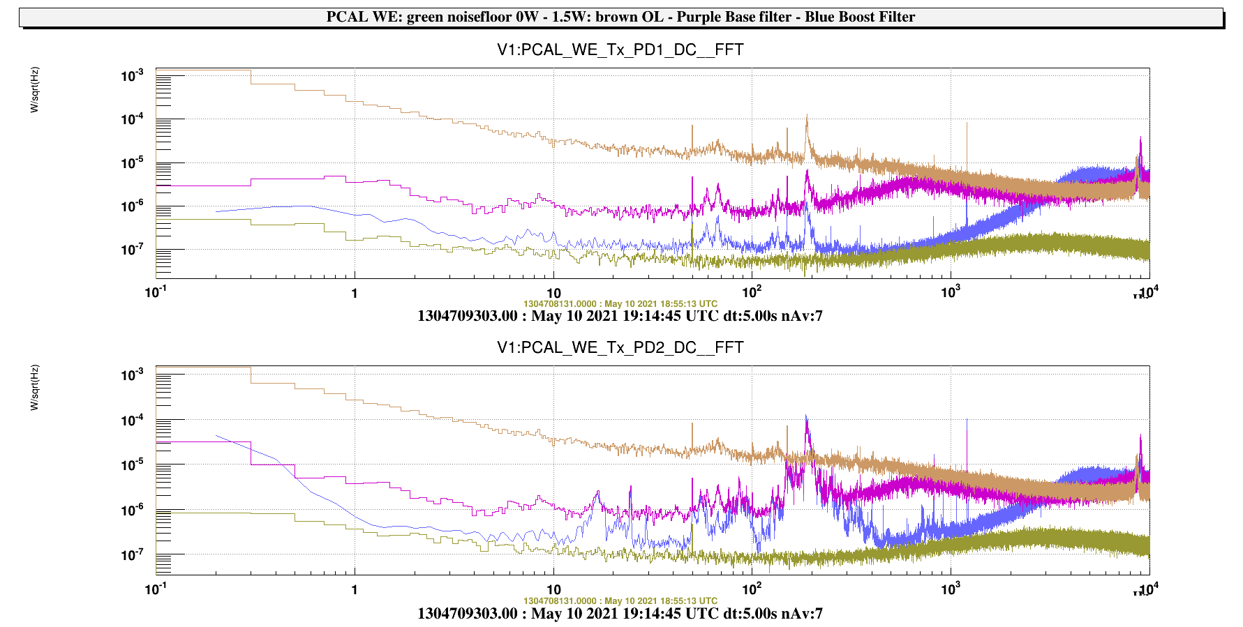
The figure https://logbook.virgo-gw.eu/virgo/uploads/51738_1620724308_PCAL_WE_InGas_1,5W-noiseFloor-OL-CL_base-CL_boost-cmp-FFT-20210510.png shows a comparaison between the fft of the output of the photodiodes, with the old and new filters.
- The control loop doesn't work when the power command is above 1.8W, We think it is due to the maximum current of the power supplier of the photodiodes.
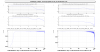
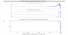
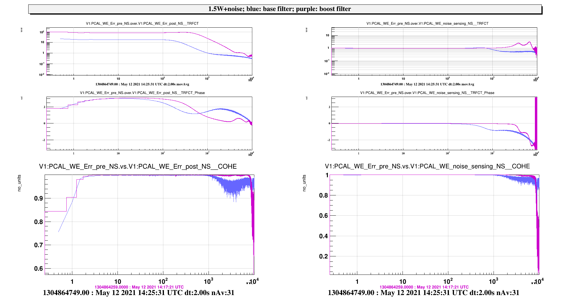
- The figure https://logbook.virgo-gw.eu/virgo/uploads/51738_1620724316_WE_loop_OLTF_CLTF.png shows the open-loop and clodes-loop-transfert-functions of the pcal, with the new filter. The laser command is 1.5W, and the is an input white noise of 1mW/sqrt(Hz).
The phase at unitary gain frequency is 1.44 radian
