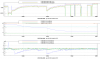
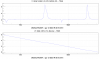
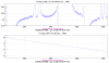
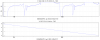
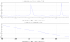
1) We first employed the already tested error signals with SC-CC beat note at 4 MHz on HD (see https://logbook.virgo-gw.eu/virgo/?r=51317). To improve the mode matching we manually adjusted the steering mirrors on SC path to bring the PZT tip-tilt actuators far from saturation. Then, with the AA loop engaged, we moved the two lenses of the SC matching telescope to maximize the value of the 4 MHz beat magnitude on the HD RF channel. Fig 1 shows the 4 MHz magnitude, the angular control voltages, and the angular error signals during the lens movement and subsequent recovery by AA. To check the mode matching, we scanned the OPA and observe the DC signal on SQZ_EQB1_IR_PD_MONI. Fig 2 shows a typical scan, where the transmission peaks of the BAB are visible above a bias due to the off-resonant reflection of the SC beam, the dips are due to the resonant coupling of SC beam into the OPA: the relative amplitude of carrier dip is around 40% (0.9V/2.2.V). Fig 3 is a vertical zoom of Fig 2: the main HOM peaks for the SC are not well visible as they partly overlap with BAB peaks. However, when the SC alignment on OPA is not optimal, the corresponding misalignment HOM peaks are quite well visible, see Fig 4 and vertical zoom in Fig 5. Fig 6 shows a scan without SC beam.
2) Since the dither lines are much more visible on the 4 MHz demodulation quadratures than on their quadrature sum (i.e. the 4 MHz magnitude) we tried to derive the angular error signals by demodulating the SQZ_EQB1_HD_DIFF_RF_4MHz_I signal instead of SQZ_EQB1_HD_DIFF_RF_4MHz_mag at dither frequencies. The resulting error signals have much higher SNR, as expected, however the sign fluctuates according to the phase of SC and CC fields, and we didn't try to close a loop with the new error signals.
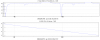
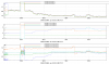
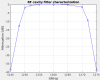
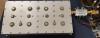
3) Afterwards we tested the baseline method for SC AA, i.e. to measure the amplitude of SC-CC beat with a RF power detector. To this purpose we first moved the SC PLL to 1.26 GHz (i.e. 60 MHz above the usual offset frequency) in order to match the design offset frequency (we demodulated the 1160 MHz SC-MAIN laser beatnote (channel 4 DDS 2) doing a 100 MHz PLL (channel 3 DDS 2)). We then aligned a fast photodiode in reflection from a flip mirror after the EQB1 FI (the flip mirror is controlled via the "IR Shutter" command in the EQB1_Thoract server on VPM); we applied a chain at photodiode output made of a RF cavity filter (BP1260-12.6-8CS, YUN Micro Electronics), centered aroud 1.26 GHz, and a RF power detector (ZX47-60LN-S+, Minicircuit), see Fig.9. Fig.8 shows the RF cavity filter characterization. The output of the power detector is acquired on DAQ channel SQZ_EQB1_HD_RF_DEMOD using a line driver. We demodulate SQZ_EQB1_HD_RF_DEMOD at the angular dither lines frequencies to get new error signals for the SC AA, and we engaged the angular control loop with such error signals. Loop parameters are still to be optimised. Fig.7 shows a locking sequence: the output of the RF power detector decreases when RF beat power increases.
We also added on EQB1_SC_AA.cfg an ACL_SWITCH_CH in order to select as error signal between HD_DIFF_RF_4MHz_mag or HD_RF_DEMOD.