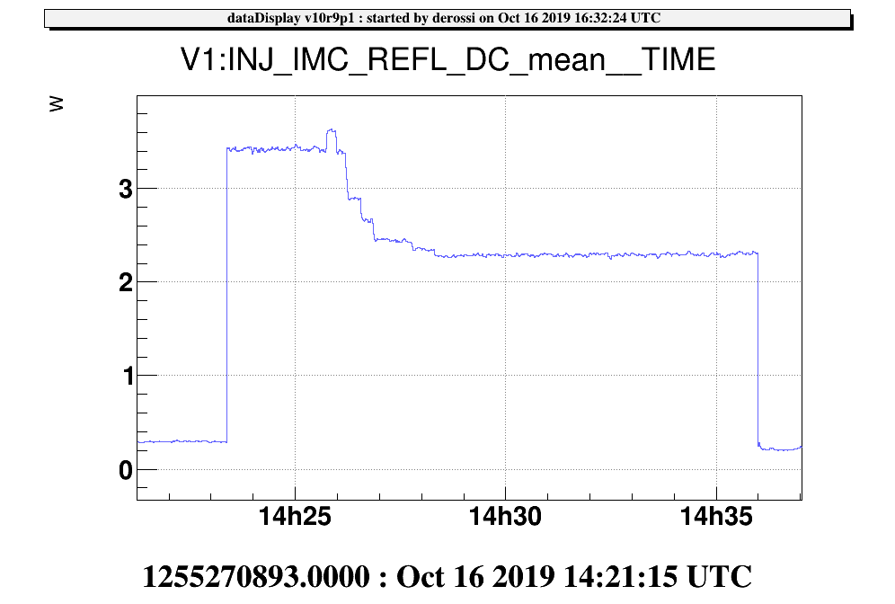
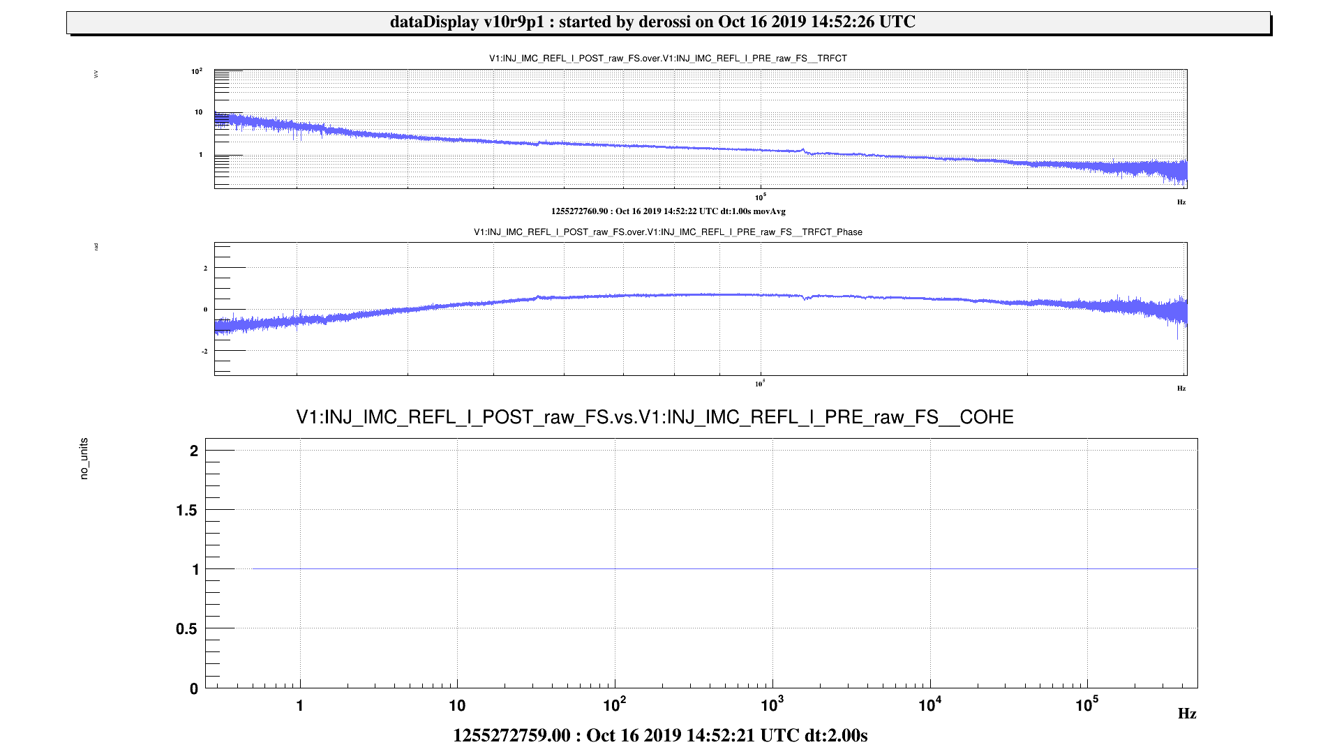
We compensated for the increase of power on the error signal photodiodes by decreasing the impinging power by a factor 1.5
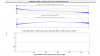
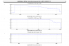
- IMC REFL PD: from 3.4 mW to 2.3 mW when the IMC is unlocked (plot 1) by tuning IPC8 (with EIBRot axis 1 ch1). We then had to compensate the gain (attenuation from 15 dB to 11 dB) in order to come back to an UGF of 130 kHz (plot 2).
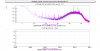
- IMC Aa quadrant photodiodes: we tuned the power on the RF quadrants with IPC 5 for the FF (EIBRot axis 1 ch 2) and with IPC 6 for the NF (EIBRot axis 2 ch 2). The quandrant in transmission which is used in DC doesn't have a rotator, so we let it as it is (it is still far from saturation). We had then to remeasure the sensing matrix
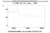
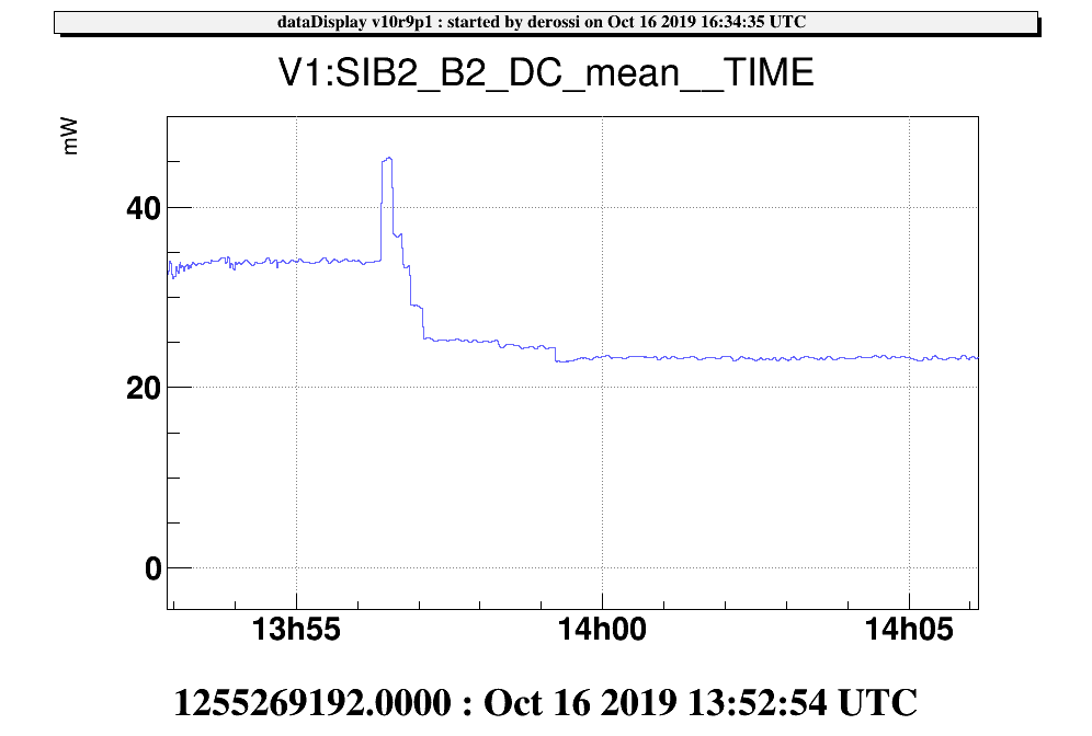
-B2: with the PR aligned we tuned the IPC3 to decrease from 31 mW to 23 mW (in the minirack in the CB)
-PSTAB: we didn't find the actuator so we let it with the gain set this morning by F. Cleva and J.P. Coulon #47250
In the table are reported the parameters of the injections to measure the IMC Aa sensing matrix
| DOF | amplitude | GPS start | duration [s] |
| IB tx | 0.4 | 1255278291 | 50 |
| IB ty | 0.5 | 1255278400 | 50 |
| IB tz | 0.3 | 1255278510 | 50 |
| MC tx | 0.8 | 1255278750 | 50 |
| MC ty | 0.4 | 1255278870 | 50 |
The effect of these operations will be better evaluated on a longer period.
